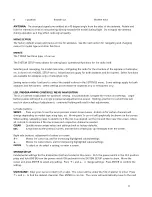
The display will show a graphic representing the switch, and the different control positions of the switch as shown
here (0, 1, and 2). The default position for "0" will always be in the down direction. The control positions of the
switch can be assigned to fit personal preference. To use the default settings, simply press ESC to confirm. To
change the control locations of the switch to be high "H", medium "M", or low "L" position, press
↑
+ or
↓ ‐
to
move the cursor to the position to be changed. Press ENTER to highlight the function at this position. Then
press
↑
+ or
↓ ‐
to change the control function. Repeat as necessary for all switch positions. Press ESC when
finished.
To remove the switch that has been set in the Control function, press ENTER to highlight the switch selection and
press CLEAR.
Other functions in this radio allow for assigning a switch to a specific function. Refer back to this section as
needed.
Offset:
Move the cursor to this function. Press ENTER, then
↑
+ or
↓ ‐
to find the percent to offset the center
position of the channel shown on this screen.
Travel:
For adjusting the maximum travel limits for a selected channel. Deflect the switch to one position and
adjust the maximum travel limit for this switch position, and then repeat for the opposite switch position.
Highlight either and press CLEAR to change back to the default setting. Press ENTER when finished.
While the output channel is being operated normally, any movement of the input channel will be mixed to-
and
also affect
the movement of the output channel.
THROTTLE CURVE:
The throttle's output is normally linear in relation to movement of the throttle stick. A non-
linear relation between the two – or curve - can allow for optimum power control in certain models or for specific
types of flying styles.
Make sure the model's full throttle position can be achieved when the throttle stick is at maximum deflection. The
throttle trim must be able to minimize throttle control completely when the throttle is at minimum.
Enter this function. Up to six points can be placed on the throttle curve, as designated next to "Point" on the
graph. Points L (low) and H (high) are each limited to a fixed range on the curve. Points 1, 2, 3, and 4 can be set if
desired with respect to the position of the throttle stick.
As the throttle stick is advanced note the point where the vertical line (throttle position) intersects the diagonal
line (curve). The coordinates of this point are shown at the bottom. The "x" (horizontal) coordinate is on the left,
and the "y" (vertical) coordinate on the right.
To set points on the curve, start at the minimum throttle position which will be noted as point "L". A point for "L"
is not marked on the graph, but is the left-most end of the curve line. The vertical position of this point can be
adjusted by moving the cursor to the RATE percentage, press ENTER then
↑
+ or
↓
- as desired. Press ENTER
when finished.
To set point 1 on the graph, advance the throttle stick until
*
shows next to "Point". Find the desired throttle stick
position and press ENTER. A
+
symbol will be placed on the curve to mark this point.
13

