


3 of 12
Variable Speed Injection Pump
The PC705-2 uses a pump to inject hot water from the boiler loop into the cool system return water. This pump is operated by the
PC705-2 at different speeds in order to inject hot boiler water at different rates into the cool system return water. For residential and
small commercial systems Taco wet rotor circulators are suitable for use as variable speed injection pumps.
Boiler Loop Pump and a Boiler Supply Sensor
The use of a boiler loop pump and boiler supply sensor allows the PC705-2 to regulate the boiler supply water temperature as well
as the system supply water temperature. If the system supply water temperature approaches a maximum setting, the control can
back off the speed of the injection pump in order to protect the system. The same also occurs when the boiler supply water
temperature approaches a minimum boiler setting.
The rate of response to sudden temperature changes by the variable speed injection system can be typically 2 to 4 times faster
than by a tempering valve or mixing valve. This faster response provides greater protection for both the system and the boiler.
PIPING OF VARIABLE SPEED INJECTION SYSTEMS
Since mixing by a variable speed injection pump is a relatively new concept, there are a few piping details which should be considered.
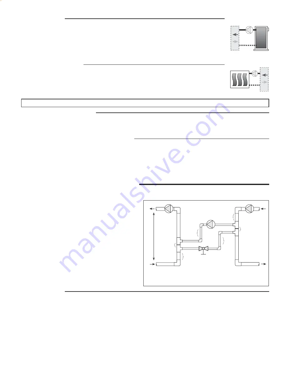
When the injection pump is turned off, there must be no heat
transfer from the boiler loop to the system loop. In order to
avoid this unwanted heat transfer, standard primary-second-
ary piping techniques are used as shown in Figure 1. This
piping arrangement requires that the injection piping be at least
one pipe diameter smaller than the piping of the boiler and
system loops. There must be no more than 4 pipe diameters
between the tees in the boiler and system loops (Note 1) in
order to prevent ghost flow when the variable speed injection
pump is off and either the boiler pump or system pump is on.
Also, there must be at least 6 pipe diameters of straight pipe on
either side of the tees (Note 2) in order to prevent the momen-
tum of water in the boiler and system loops from pushing flow
through the injection loop. Finally, there should be a minimum
1 foot drop to create a thermal trap (Note 3) in order to prevent
convective heat transfer through the injection loop.
Design Procedure
1) Determine the design operating temperatures of the heating system loop and boiler. (Ts and Tb from figure 1.)
2) Determine the flow rate and design temperature drop (
∆
Ts) in the system loop when all zones are turned on. If one of these
variables is unknown, use Equation 1 or 2 to calculate the other variable.
3) Compute Tb - Ts. Look up the flow ratios on Figure 2.
4) The design injection flow rate for direct injection is calculated from Equation 3. If the injection flow rate is greater than 45 US GPM,
it may be necessary to use a 4-way mixing valve instead of a variable speed injection system.
5) Decide whether or not to include a balancing valve in the injection piping. A balancing valve allows adjustment when the injection
pump is larger than needed. A balancing valve also provides the possibility of manual operation of the heating system by turning
the injection pump fully on and adjusting the balancing valve to obtain the desired system supply water temperature.
6) The injection piping size and model of pump to install can now be looked up in Figure 3. Don't oversize the injection system. If
the heating system is not able to get enough heat, the boiler's operating temperature can be increased. This may be done
automatically by the PC705-2 when the boiler sensor is used.
Boiler Protection
Cool water is often returned to the boiler from low temperature radiant floor heating systems or when the
heating system is recovering from night setback. This cool boiler return water may cause the boiler to operate
at such a low temperature that the flue gases condense. Alternatively, when the boiler surfaces are hot due
to previous loads such as domestic hot water generation, the large temperature difference (
∆
T) between the
boiler and its return water can cause the boiler to become thermally shocked. Proper protection of the boiler
under these circumstances requires a modulating mixing device that can temporarily reduce the heating load.
This is normally accomplished by closing a valve or reducing the speed of an injection pump.
Maximum System Supply
Some systems, such as hydronic radiant floor heating, usually operate at water temperatures that are below
the minimum boiler supply temperature. This is due to the large surface area of the floors which radiate a
significant amount of heat at low water temperatures. Floor heating systems also have a maximum floor
surface temperature limit for occupant health reasons and to protect the materials within the floor. In such
systems a modulating mixing device is normally required to limit the supply water temperature.
Mix
Mix
Variable Speed Injection
Fig. 1
Balancing
Valve
Boiler
Loop
System
Loop
(Ts)
(Tb)
Variable Speed
Injection Pump
∆
Ts
Tb
= Boiler supply temperature
Ts
= System supply temperature
∆
Ts = System temperature drop (Typically 20
°
F for
convectors and 10
°
F for radiant floor heating)
Note 3
Note 1
Note 2
Note 3
Note 1
Note 2


