


0-003-2063-2 (EN)
2 (8)
Designation
Explanation
Part number
M800
modulating control signal or increase/decrease signal
880-0310-030
M800-S2
modulating control signal or increase/decrease signal and end point switches
880-0311-030
M800-STS
modulating control signal or increase/decrease signal and self testing
safety device
880-0312-040
M800-S2-STS
modulating control signal or increase/decrease signal with end point switches
and self testing safety device
880-0313-040
The actuator
The brushless DC-motor of the actuator
turns a screw via a gear wheel. The
motor receives a control signal from a
controller. The screw gets a linear
movement which moves the stem of the
valve.
Control signal
M800 can either be controlled by an
increase/decrease signal or by a
variable direct voltage.
If an increase/decrease signal is used,
the actuator normally moves inwards on
an increase signal and outwards on a
decrease signal, see Settings.
Manual operation
There is a manual operation handle on
the actuator, see figure 2. When it is
lowered, the motor stops. Then, the
actuator can be operated manually if
the handle is turned.
Position feedback
Forta actuators are equipped with a 2–
10 V DC position feedback signal,
where 2 V always corresponds to the
closed position and 10 V to the open
position.
End point switches
When actuators are controlled in
sequence, it is possible to use the end
point switches that have set positions.
They will toggle when the valve is fully
open or fully closed, respectively.
Figure 2
Manual
operation
handle
PART NUMBERS
FUNCTION
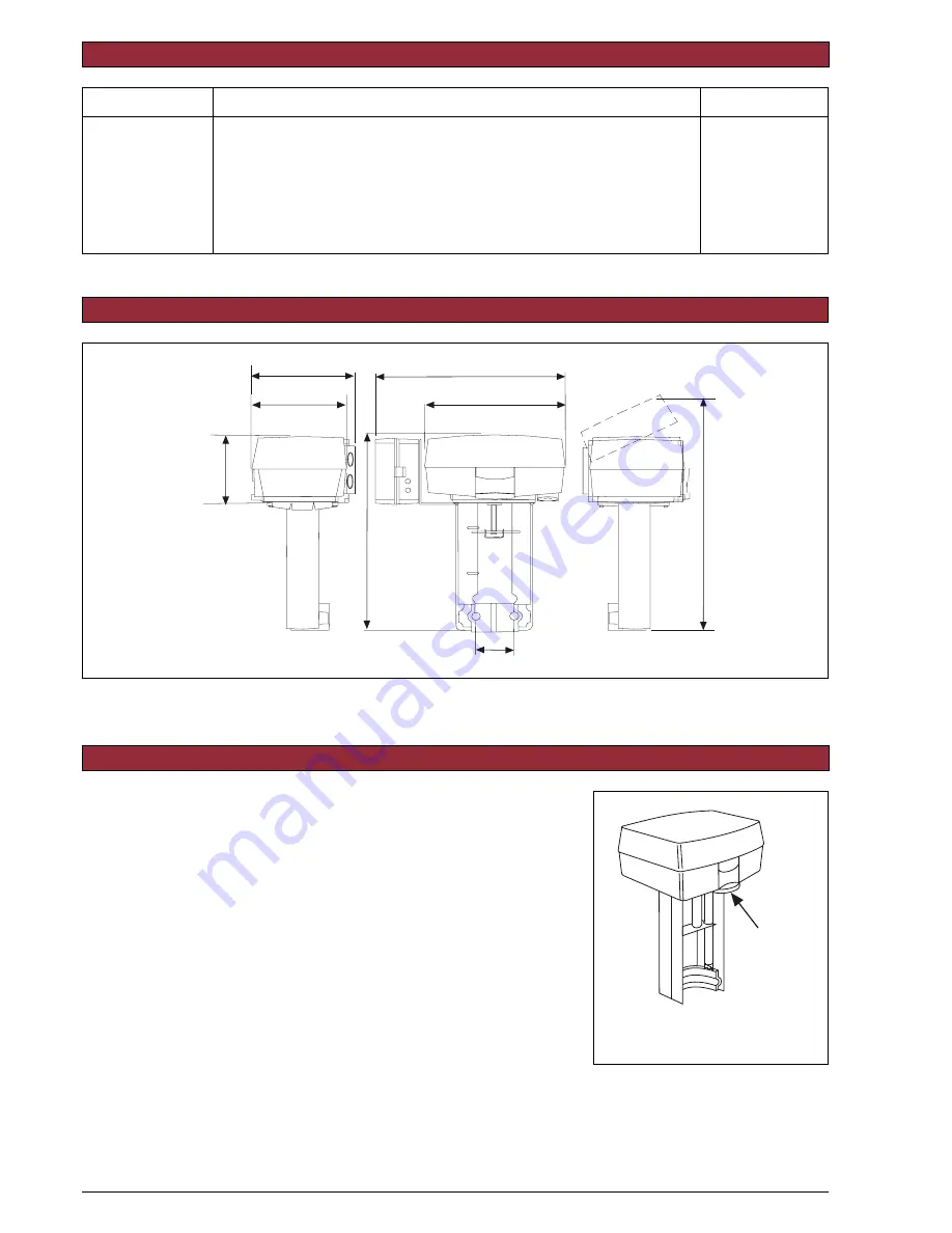
Figure 1
DIMENSIONS
173
44
315
82
243
117
(6.81)
(4.60)
(9.57)
(3.235)
(1.73)
(12.40)
137
(5.39)
238 (9.37)
Mått: mm
Dimensions: (in.)


