


7 (8)
0-003-2063-2 (EN)
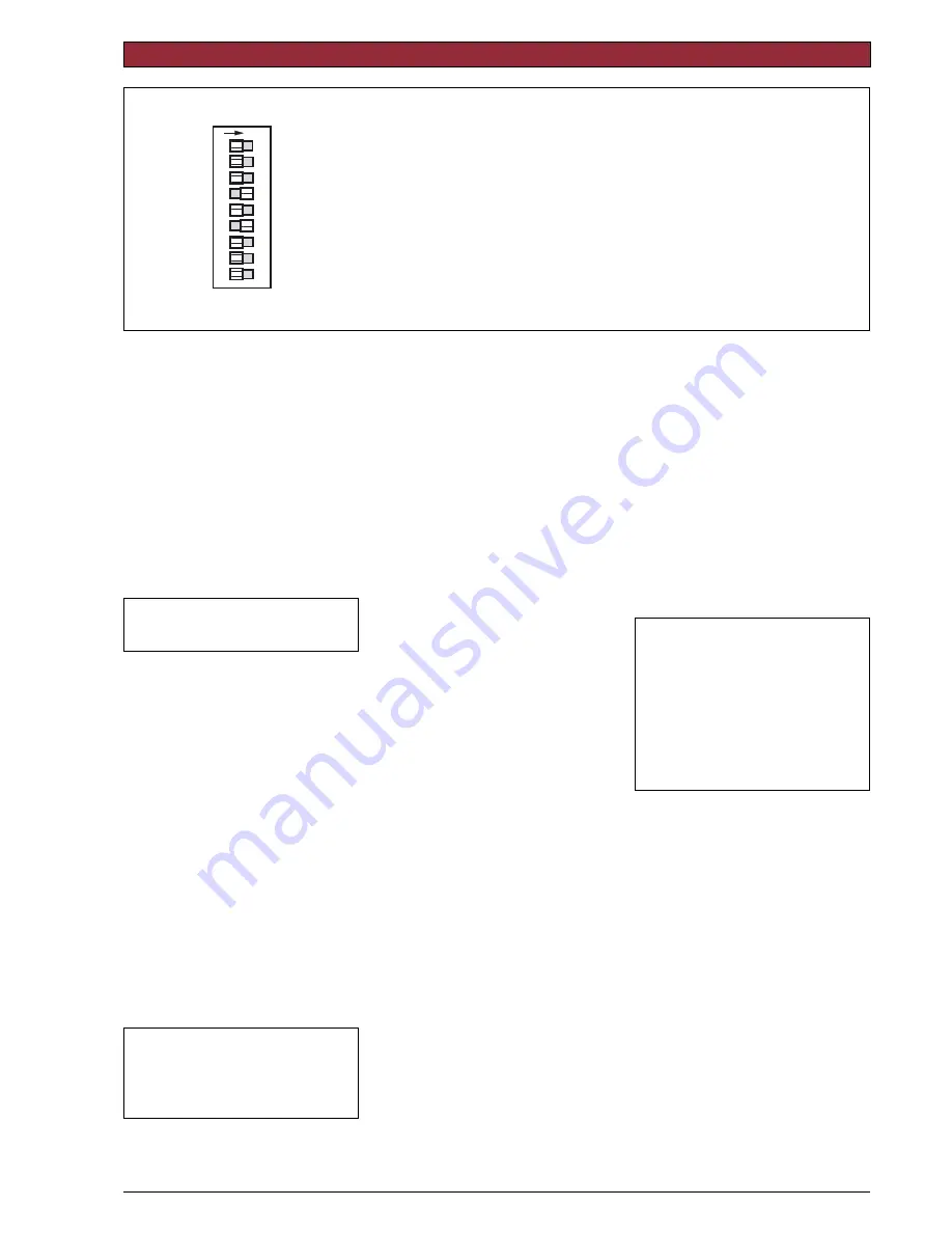
SETTINGS
INC
0-5, 2-6
ADJ
LIN/LG
INV
300 s
2-10
5-10, 6-10
SEQ
OP
NORM
NORM
60 s
0-10
– – –
MOD
12
3
4
5
6
7
8
O
N
9
OUT
IN
Figure 8
Function in the
Description
“OFF” pos.
“ON” position
1
In
Out
Valve closing screw direction
2
Modulating
Increase/decrease
Control (not at Sequence)
3
–
Sequence
Sequence control
4
0-10 V
2-10 V
Voltage range
5
0-5 V, 2-6 V
5-10 V, 6-10 V
Part of voltage range
6
60 s
300 s
Running time
7
Normal
Inverted
Direction of movement
8
Normal
Linear/Logarithmic
Valve characteristic
9
Operation
End position adjust (mom.)Operation/End position adjustment
There are nine switches in a row on the
circuit board. On delivery (’Factory’), all
switches are in the “OFF” position.
1
Valve Closing Screw Direction—
IN / OUT
IN direction of movement is used when
the screw of the actuator moves
inwards to close the valve.
OUT direction of movement is used
when the screw of the actuator moves
outwards to close the valve.
Note!
At power failure, the STS
closes according to this switch.
Y = 2 V at close valve.
2
Control signal—MOD / INC
TAC Forta can either be controlled by a
variable direct voltage, a so called
modulating signal (MOD), or by an
increase/decrease signal (INC).
3
Sequence or parallel control—
– – – / SEQ
With sequence (or parallel) control
(SEQ), two actuators/valves can be
controlled by only one control signal.
For each of these you can choose
which part of the voltage range to use,
the upper one, 5-10 V (6-10 V) or
the lower one, 0-5 V (2-6 V).
If the switch NORM / INV is in the
NORM position, the higher voltage
corresponds to 100% flow and the
lower one to 0%.
With NORM / INV in the INV position
you will get the opposite function.
Note!
If sequence or parallel control
is
not
used, the switch – – – / SEQ
must be in the
OFF position, as the
switch MOD / INC is not valid during
sequence or parallel control.
4
Voltage range—0-10 / 2-10
You can choose whether to use the
control signal voltage range 0-10 V or
2-10 V.
5
Part of voltage range—
0-5, 2-6 / 5-10. 6-10
You can choose which part of a voltage
range to use, the lower one 0-5 V
(2-6 V) or the upper one 5-10 V
(6-10 V).
If the switch is in the NORM position,
the higher voltage corresponds to 100%
flow and the lower one to 0%. To
achieve the opposite function, the
switch should be put in its INV position.
6
Running time—60 s / 300 s
With increase/decrease control, you can
choose a running time between 60 s or
300 s.
With modulating control, the running
time is always 15 s / 20 s / 30 s.
7
Direction of movement—
NORM / INV
When normal direction of movement is
used, the screw of the actuator moves
inwards when the control voltage
decreases or if the actuator gets a
decrease signal.
With the switch NORM / INV, the
direction of movement can be changed.
8
Linearization—NORM / LIN/LG
The motorized valve characteristics can
be modified. If you wish for the
characteristics to be affected, the
setting LIN/LG will make the
characteristics of an equally modified
percentage (EQM) valve almost linear.
On the other hand, with LIN/LG a
motorized valve equipped with a linear
valve will operate with ”Quick open
characteristics”. This means that with a
small control signal, the valve will be
almost completely open.
Note!
For the actuator to register
new settings of the switches, the
supply voltage must be cut or the
manual operation handle lowered,
the settings done, and then the
handle raised again.
Please refer to illustration on page 2.
(This does not apply to the switch
OP/ADJ).
9
End position adjustment—
OP / ADJ
This switch is only used to adjust the
end positions when the actuator is
commissioned.
Momentarily put the switch in the ON
position. The actuator will automatically
find the end positions of the valve.


