Annex
10—3
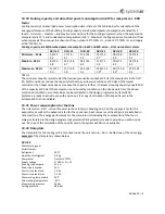
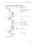
10.7
Menu
–
drawing
of
the
menu
to
guide
the
user
Drawing
of
the
menu
appears
from
section
12
10.8
The
start
display
The
start
picture
shown
when
the
potentiometer
has
not
been
activated
for
10
minutes
In:
nnn%
shows
the
capacity
ordered
by
the
main
air
handling
unit
controller.
Out:
nnn%
shows
the
capacity
ordered
by
this
internal
controller
‐
LMC251
–
of
the
compressor.
10.9
Settings
About
basic
settings
in
the
submenus
in
the
LMC251
10.10
Automatic
resets
of
the
high
pressure
switch
This
is
about
the
maximum
number
of
automatic
resets
of
the
high
pressure
switch
that
are
acceptable
within
one
hour.
If
this
number
is
exceeded,
the
unit
will
be
shut
down
until
the
high
pressure
switch
has
been
reset
manually.
10.11
Polarity
The
Alarm
polarity
can
be
set
to”Normally
Open”
or
”Normally
Closed”.
10.12
Hotgas
–
setting
of
period
This
is
the
number
of
seconds
that
the
hotgas
valve
is
open.
The
period
is
relatively
long,
but
the
supply
temperature
is
not
oscillating
at
all
and
the
stability
of
the
supply
temperature
is
sufficient.
The
number
of
seconds
is
a
factory
setting
that
should
not
be
reduced.
Reduction
of
the
number
of
seconds
will
not
improve
the
stability
of
the
temperature
to
a
degree
that
can
be
proven
by
measurements.
If
the
number
of
seconds
is
reduced,
the
number
of
times
that
the
valve
is
opened
and
closed
will
be
increased
–
maybe
considerably,
and
the
valve
could
be
worn
out
prematurely.
10.13
Limiter
DeltaMax
is
the
maximum
acceptable
change
in
%
/
second
of
the
actual
cooling
capacity.
10.14
Service
In
this
menu
information
about
the
software
version
in
the
controller
as
well
as
2
submenus
–
“Manual
operation”
and
“Runtime”
10.15
Manual
operation
When
the
menu
–
Manual
operation
‐
is
activated,
the
technician
is
able
to
control
the
operation
manually,
when
the
start
signal
from
the
main
air
handling
unit
controller
is
on
(start
signal
is
just
potential
free
connection
of
the
two
terminals
–
3&4).
This
procedure
is
relevant
for
the
test
during
the
annual
maintenance
with
the
control
of
all
safety
and
regulation
procedures
or
after
installation
of
new
components.
If
no
new
settings
have
been
carried
out
on
the
controller
for
10
minutes,
the
menu
–
Manual
operation
–
is
deactivated,
and
the
unit
returns
to
the
automatic
mode.
10.16
Running
hours
and
hotgas
activations
In
this
menu
the
number
of
running
hours
for
the
compressor,
and
the
number
of
activations
of
the
hotgas
valve
can
be
read.
This
information
is
valuable
for
the
maintenance.
10.17
Alarm
10.17.1
Alarm
Show
the
actual
alarm
with
alarm
number.
Summary of Contents for Danvent DV
Page 28: ...Bilag 8 8...
Page 33: ...Annex 9 5...
Page 36: ...Annex 9 8 9 3 Assemble divided rotor for DV 60 DV 80 DV 100 DV 120 og DV 150...
Page 37: ...Annex 9 9...
Page 38: ...Annex 9 10...
Page 39: ...Annex 9 11...
Page 40: ...Annex 9 12...
Page 41: ...Annex 9 13...
Page 42: ...Annex 9 14...
Page 43: ...Annex 9 15...
Page 44: ...Annex 9 16...
Page 45: ...Annex 9 17...
Page 46: ...Annex 9 18...
Page 47: ...Annex 9 19 9 4 Assemble divided rotor for DV 190 og DV 240...
Page 48: ...Annex 9 20...
Page 49: ...Annex 9 21...
Page 50: ...Annex 9 22...
Page 51: ...Annex 9 23...
Page 52: ...Annex 9 24...
Page 53: ...Annex 9 25...
Page 54: ...Annex 9 26...
Page 55: ...Annex 9 27...
Page 56: ...Annex 9 28...
Page 57: ...Annex 9 29...
Page 58: ...Annex 9 30...
Page 71: ...Annex 12 3...
Page 75: ...Annex 12 7...


