


Annex
9—2
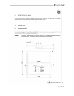
The
factory
sets
the
positions
of
the
4
DIP
switch
levers
for
the
maximum
of
20
revolutions
per
minute
for
sorption
exchangers.
The
position
of
each
DIP
switch
lever
is
shown
below.
DV
Diameter
of
pulley
DIP
switch
position
Motor
10
50
1000
90TYD
‐
S214
‐
M
2.8Nm
15
87
0100
120TYD
‐
S214
‐
M
5.5Nm
20
87
25
107
30
107
40
107
1100
50
118
60
118
80
140
1010
120TYD
‐
S214
‐
L
7.5Nm
100
150
120
150
0110
150
160
190
160
240
160
9.1.2
Indication
of
operation
mode
via
red
and
green
LED
as
well
as
test
of
motor
The
LED
is
in
the
cover
of
the
cabinet.
LED
indication
Value
No
indication
Power
off
Green
Ordinary
operation
Green
–
flashes
Ready
for
operation
Constant
green
and
red
indication
for
activated
rotor
guard
Magnet
on
the
rotor
has
activated
rotor
guard
Constant
green
and
fast
red
flashes
Restart
sequence
active
Red
Rotor
guard
has
not
been
activated
Number
of
red
flashes
in
series
Value
1
Output
current
limit
2
Over
voltage
3
Under
voltage
4
Failure
in
the
controller
5
Communication failure
Summary of Contents for Danvent DV
Page 28: ...Bilag 8 8...
Page 33: ...Annex 9 5...
Page 36: ...Annex 9 8 9 3 Assemble divided rotor for DV 60 DV 80 DV 100 DV 120 og DV 150...
Page 37: ...Annex 9 9...
Page 38: ...Annex 9 10...
Page 39: ...Annex 9 11...
Page 40: ...Annex 9 12...
Page 41: ...Annex 9 13...
Page 42: ...Annex 9 14...
Page 43: ...Annex 9 15...
Page 44: ...Annex 9 16...
Page 45: ...Annex 9 17...
Page 46: ...Annex 9 18...
Page 47: ...Annex 9 19 9 4 Assemble divided rotor for DV 190 og DV 240...
Page 48: ...Annex 9 20...
Page 49: ...Annex 9 21...
Page 50: ...Annex 9 22...
Page 51: ...Annex 9 23...
Page 52: ...Annex 9 24...
Page 53: ...Annex 9 25...
Page 54: ...Annex 9 26...
Page 55: ...Annex 9 27...
Page 56: ...Annex 9 28...
Page 57: ...Annex 9 29...
Page 58: ...Annex 9 30...
Page 71: ...Annex 12 3...
Page 75: ...Annex 12 7...