background image

D200-100-00

1

I56-3888-005

CONTENTS

Introduction .  .  .  .  .  .  .  .  .  .  .  .  .  .  .  .  .  .  .  .  .  .  .  .  .  .  .  .  .  .  .  .  .  .  .  .  .  .  .  . 1
The FAAST LT Functional State Diagram .  .  .  .  .  .  .  .  .  .  .  .  .  .  .  .  . 1

Password Procedure (to enter Maintenance Mode) 

2

An Introduction to PipeIQ™   .  .  .  .  .  .  .  .  .  .  .  .  .  .  .  .  .  .  .  .  .  .  .  .  .  .  . 2

Using PipeIQ™ to Configure and Monitor FAAST LT

 .  .  .  .  .  .  .  . 2

Connecting a PC to a FAAST Device for the First Time 

2

Preparing to Configure or Monitor a FAAST LT Device 

3

Monitoring a FAAST LT Device 

3

Important Notes on Altering FAAST LT Settings 

3

Configuring a FAAST LT Device 

3

Sending a Configuration to a FAAST LT Device 

4

Time and Date: Setting the Real Time Clock 

4

Setting the Alarm Level (Stand Alone Versions Only) 

4

FAAST LT Alarm Mode (Loop Based Versions Only) 

4

Setting the FAAST LT Device Fan Speed 

4

FAAST LT


FIRE ALARM ASPIRATION SENSING TECHNOLOGY

®

ADVANCED SET-UP AND CONTROL GUIDE

INTRODUCTION

The FAAST LT aspirating smoke detector is an advanced smoke 

sensing system for use in early warning and very early warning 

applications . The system continuously draws air from the controlled 

environment through a series of sampling holes to monitor the 

environment for smoke particulate . A range of sensing, operating 

and output facilities can be configured in the FAAST LT unit by the 

end user . This is accomplished by programming and downloading 

control parameters from a PC running the proprietary software 

application, 

PipeIQ™ 

(Version  2.3  and  above).  This  manual 

describes  how  to  monitor  and  configure  the  various  operating 

parameters available in a FAAST LT unit via the user interface 

provided by PipeIQ™ . 

Further PipeIQ™ Capabilities .  .  .  .  .  .  .  .  .  .  .  .  .  .  .  .  .  .  .  .  .  .  .  .  .  . 5

Creating a Project 5
Designing a Pipe Layout 5
Creating Reports 5
PipeIQ™ Help 5

Appendices

A: FAAST LT Config. Parameters and Default Set-Up Values

  . 6

Configuration Parameters


6

Default Set-Up Values - Stand Alone Versions 

10

Default Set-Up Values - Loop Based Versions 

12

B: FAAST LT Fault Codes .  .  .  .  .  .  .  .  .  .  .  .  .  .  .  .  .  .  .  .  .  .  .  .  .  .  .  .  .

14

C: Example Pipe Configurations

 .  .  .  .  .  .  .  .  .  .  .  .  .  .  .  .  .  .  .  .  .  .  .  .16

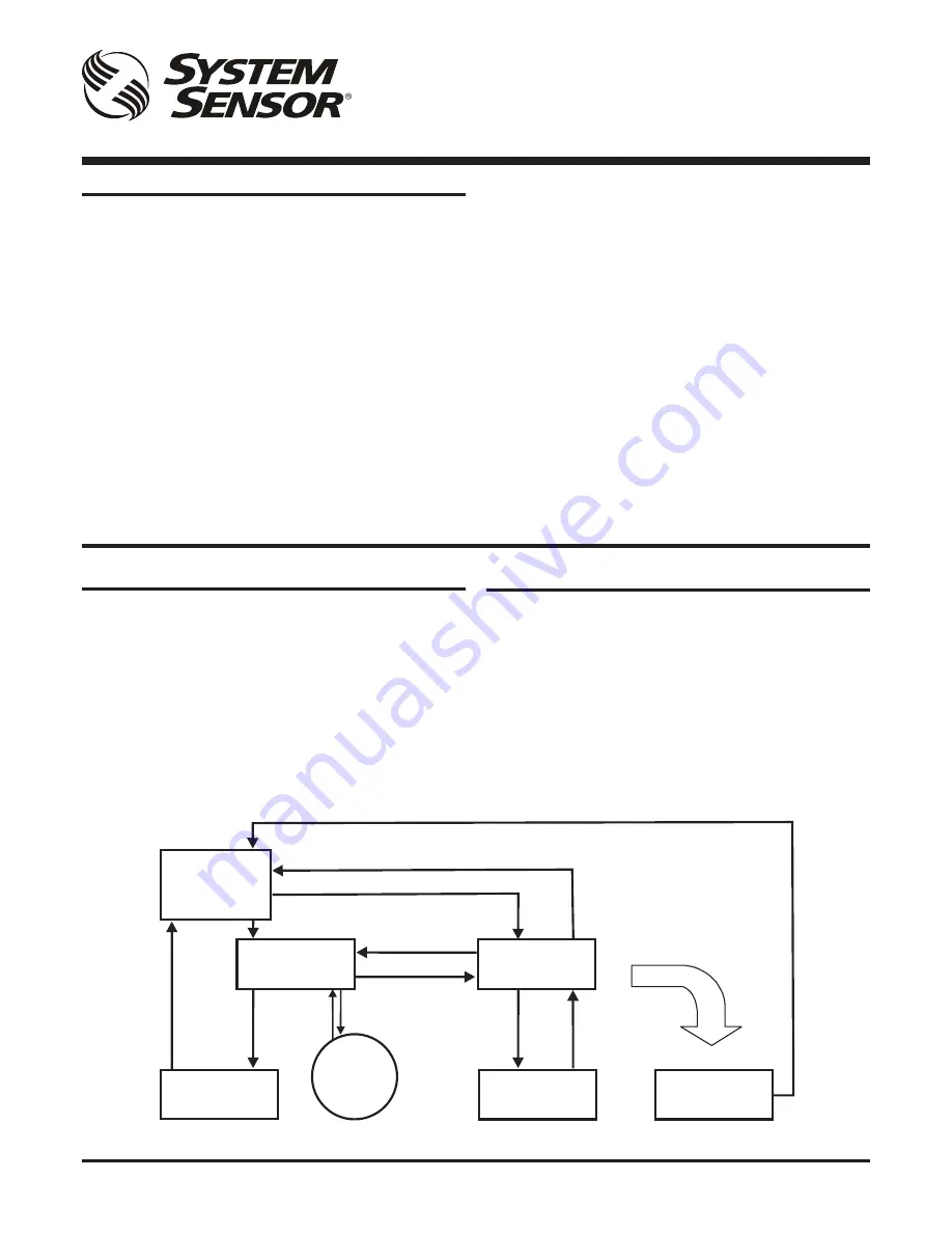
THE FAAST LT FUNCTIONAL STATE DIAGRAM.

In operation, the device can be in one of 6 possible states: 

Initialization
Normal
Maintenance
Remote Maintenance
Service Mode
Power Out Of Range state

The routes in and out of these states are shown in the diagram 

below .

MAINTENANCE

REMOTE

MAINTENANCE

SERVICE

MODE

POWER OUT OF

RANGE STATE

Power < 18V
Power > 32V

(Power-ON)

INITIALIZATION

NORMAL

DISPLAY

FAN

SPEED

USB

Disconnected

+ Cover Close

Cover Open +

USB

Connected

RESET +
DISABLE

RESET +

Password Enter

Cover

Open

Cover

Close

RESET + Password Enter (During Auto Speed Procedure)

Maintenance Timeout or after TEST + RESET + DISABLE (When Device Configuration has been Changed)

Maintenance Timeout or after

TEST + RESET + DISABLE

(No Need for Device to Initialize)

Power in Correct Range

Keep this document for future reference

Summary of Contents for FAAST LT

Page 1: ...control parameters from a PC running the proprietary software application PipeIQ Version 2 3 and above This manual describes how to monitor and configure the various operating parameters available in...

Page 2: ...ice is in Normal the Service Mode state is entered automatically when the front cover is opened The FAAST LT unit switches off the power to the unit Once the service action is complete and the front c...

Page 3: ...purposes only Manually setting the fan speed to change the air flow will not alter the associated hi lo flow limit settings in the FAAST LT unit Therefore this option should not be used to set or cha...

Page 4: ...el 6 0 50 obs ft 1 64 obs m Level 7 1 00 obs ft 3 28 obs m Level 8 1 50 obs ft 4 92 obs m Level 9 2 00 obs ft 6 56 obs m To set these levels ensure the Configuration tab is selected in the left pane a...

Page 5: ...ions see the PipeIQ Help Menu PipeIQ Help The online help is a guide through the PipeIQ application The Help opens in a separate window where it is possible to search and navigate to information on di...

Page 6: ...r 2 enabled YES NO 8 Daylight saving enabled YES NO AUTO Allows the real time clock date to change for a daylight saving period 1 hour NO Daylight saving off YES period is specified by parameters 9 an...

Page 7: ...t sets the fan speed to reach the reference flow programmed in the device In Manual mode the user can set the fan speed Use PipeIQ LT to change default configuration of the reference flow both modes a...

Page 8: ...ated by external input Note that only one action can be selected at a time Note External input only active in NORMAL state 50 External input silences sounders YES NO 51 External input resets device YE...

Page 9: ...ethod used to indicate an alarm SENSOR MODE When remote output on a sensor is set ON for configured time that sensor channel goes into alarm When the remote output turns OFF the channel stops signalli...

Page 10: ...YES 19 Channel 2 alarm is latched YES NO YES YES YES 20 Alarm delay 0 240 s 0 0 0 21 Auxiliary relay is used for channel 2 faults YES NO YES YES YES 22 Channel 1 label 16 char ASCII code from 32 to 12...

Page 11: ...MI 17 00 17 00 17 00 60 Holiday day 1 date DD MM empty empty empty DD MM empty empty empty 79 Holiday day 20 date DD MM empty empty empty 80 Sounder activation mode On Pre alarm On Alarm Alarm Alarm A...

Page 12: ...32 to 127 X X 2 24 Channel 1 fan speed mode Manual Auto Auto Auto Auto 25 Channel 2 fan speed mode Manual Auto X X Auto 26 Channel 1 manual fan speed 0 10 X X X 27 Channel 2 manual fan speed 0 10 X X...

Page 13: ...Sounder activation mode On Pre alarm On Alarm X X X 81 Day night mode enabled YES NO X X X 82 Monday is holiday YES NO X X X 83 Tuesday is holiday YES NO X X X 84 Wednesday is holiday YES NO X X X 85...

Page 14: ...t X X User can configure a specific delay between fault condition and fault indication 0 240 s Fault F013 HIGH FLOW FAULT CH1 Channel 1 flow is over the configured limit X X User can configure a speci...

Page 15: ...feet X Please clean the sensor Alert A009 COMPENSATION 0 6 DIRTY ALERT S1 The sensor 1 chamber is very dirty 0 6 feet X Please clean the sensor Alert A010 DRIFT LIMIT ALERT S1 The sensor 1 chamber is...

Page 16: ...2 2 2 3 2 4 2 5 2 6 2 5 2 5 7 8 9 2 5 10 2 5 FAN SPEED 10 2 5 11 12 13 2 5 14 3 15 3 16 3 17 3 5 18 3 5 3 5 END 4 4 Example Pipe Configuration 1 Channel Single Pipe 100m x 18 Holes Class C Hole 2 Hol...

Page 17: ...ing 5 10 10 10 10 10 10 5 4 8 75m 0 2 75m HOLE SIZE mm 1 2 5 2 2 5 3 2 5 4 3 5 3 6 3 7 3 8 3 9 3 10 3 11 12 13 14 15 16 17 18 END END HOLE Typical Example Pipe Configuration 1 Channel T Piece 2 Pipes...

Page 18: ...Configuration 1 Channel Single Pipe With Filter Class C FILTER HOLE SIZE mm 1 3 5 2 4 3 3 4 3 5 3 5 END 3 5 Hole 4 Hole 3 Hole 2 Hole 1 5 3 5 6 7 3 5 6 Hole 6 6 6 6 6 Hole 7 6 6 End hole FAN SPEED 6 3...

Page 19: ...D200 100 00 19 I56 3888 005 System Sensor Europe Pittway Tecnologica S r l Via Caboto 19 3 34147 TRIESTE Italy http www systemsensoreurope com...

Reviews: