


| 13
a switch which controls switching on and setting spot and pulse functions.
This type is supplied with a digital voltampermeter in a standard way.
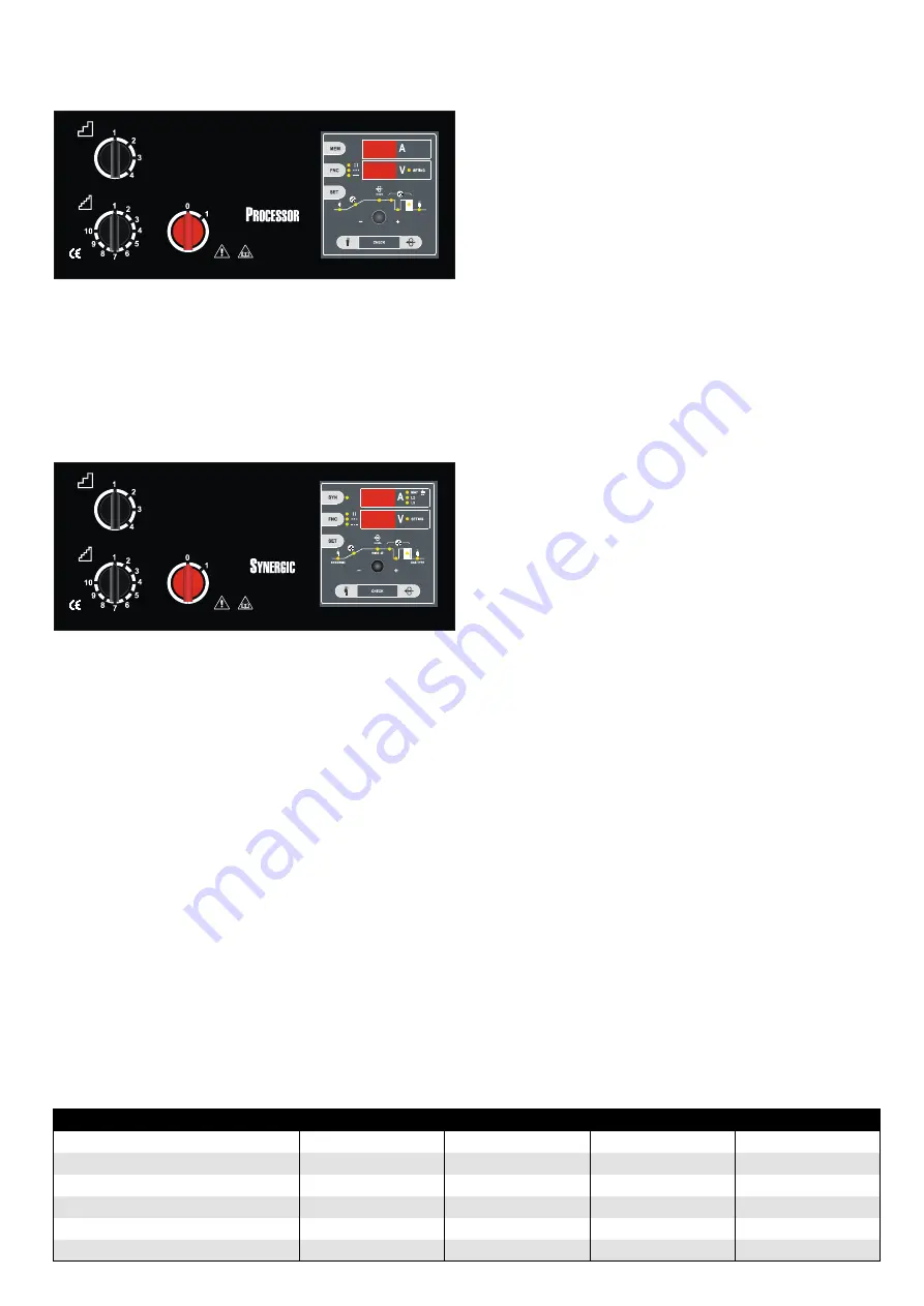
Digital type PROCESSOR
Simple solution for all MIG / MAG welding functions. All values are cont
-
rolled and set by one potentiometer and two buttons. The lOGIC function
contributes to simplicity of operation. The machines are equipped with a
digital volt-ampere meter with memory. The control allows setting the va
-
lues of pre-gas / post-gas, SOFT START function, wire burn-out, scoring and
pulsation, two-stroke and four-stroke modes. Progressive wire feed. Electro
-
nic wire feed speed control with feedback feed control ensures a constant
set speed.
Synergic type SYNERGIC (400, 500 only)
Significantly simplifies the setting of welding parameters. by simply adjus
-
ting the welding wire diameter and protective gas used, the operator de
-
termines the type of program. Then set the voltage with the switch and
the Synergic control unit selects the most suitable wire speed parameters.
For control and adjustment of all values serves one potentiometer and two
buttons. The lOGIC function contributes to simplicity of operation. The ma
-
chines are equipped as standard with a digital volt-ampere meter with me
-
mory. The control allows setting the values of pre-gas / post-gas, SOFT START
function, wire burn-out, spoting and pulsation, two-stroke and four-stroke
modes. Progressive wire feed. Electronic wire feed speed control with feed
-
back feed control ensures a constant set speed.
machines are standardly equipped with:
• 3 m ground cable with clamp
• Gas connection hose
• Rolls for wire diameters of 1.0 and 1.2 mm
• The accompanying documentation
• Reduction for 5 kg and 18 kg wire
• Spare fuses for gas heating source
• Digital volt-ampere meter with memory (informative meter only)
• Features pre-gas, post-gas, SOFT START and burn-out
• Two stroke and four stroke functions
• Spoting and slow pulsation modes
• Four-roll wire feeder
13
• liquid circle (WS variant only)
• Jumper of liquid cooling connectors (WS only)
Special accessories for ordering:
• Welding torches 3, 4 and 5 m long
• Reduction valves for CO
2
or Argon mixed gases
• Spare rolls for different wire diameters
• burner spare parts
• Grounding cable length 4 - 5 m
• Wire straightener
Installation
The installation site for the system must be carefully chosen in or
-
der to ensure its satisfactory and safe use. The user is responsi-
ble for the installation and use of the system in accordance with the produ
-
cer´s instructions contained in this manual.
before installing the system the user must take into consideration the po
-
tential electromagnetic problems in the work area. In particular, we suggest
that you should avoid installing the system close to:
• Signalling, control and telephone cables
• Radio and television transmitters and receivers
• Computers and control and measurement instruments
• Security and protection devices.
Persons fitted with pacemakers, hearing aids and similar equipment must
consult their doctor before going near a machine in operation. The equip
-
ment´s installation environment must comply to the protection level of the
frame i.e. IP 21. The system is cooled by means of the forced circulation of
air, and must therefore be placed in such a way that the air may be easily
sucked in and expelled through the apertures made in the frame.
Connection to the electrical supply
Before connecting the welder to the electrical supply check, that the ma-
chines plate rating corresponds to the supply voltage and frequency and
that the line switch of the welder is in the position „0“.
Use original plug for machines to connect to power supply.
Machines are designed for TN-C-S grid. It´s provided with 5-pin plug. The
middle line wire is not used.
Eventual changing of plug can be made only by person with electrotechnical
qualification and standard ČSN 332000-5-54 article 546.2.3 must be kept,
that means middle line wire and protective line wire must not be linked.
If you need to change the plug, follow this:
Connection to the power supply must be carried out using of four polar ca
-
ble
• three conducting wires, it does not matter, what is the order of phases
• the fourth, yellow-green wire is used for making the „EARTH“ connection.
connect a suitable normalized plug to the power cable. Provide for an
electrical socket complete with fuses or an automatic switch.
TABLe 2
shows the recommended load values for retardant supply fuses
chosen according to the maximum nominal current supplied to the welder
and the nominal supply voltage.
NOTe 1:
Any extensions to the power cable must be of a suitable diameter,
and absolutely not of a smaller diameter than the special cable supplied
with the machine.
NOTe 2:
Given the size of the installed capacity, the approval of the distribu
-
tion plants is required to connect the equipment to the public distribution
network.
Table 2
Type
400 W
500/500 W
4000W
5000W
I Max
350 A (35 %)
450 A (45 %)
350 A (35 %)
450 A (35 %)
Installed power
13.5 kVA
18.6 kVA
16 kVA
18.8 kVA
Protection
25 A
32 A
25 A
32 A
Diameter of input connection
4 x 2.5 mm
2
4 x 2.5 mm
2
4 x 2.5 mm
2
4 x 2.5 mm
2
Earth cable – cut
35 mm
2
50 mm
2
35 mm
2
50 mm
2
Recommended welding torch
KTb 401
KTb 501
KTb 401
KTb 501
EN


