


20
|
20
function LOGIC
(only with machines PROCESSOR and SyNERGIC)
Function lOGIC includes a file of simplifying and clarifying points which pre
-
sent adjusted and currently set values.
If two displays show a few different parameters, it is necessary to simplify
presentation of parameters. Function lOGIC operates just in this way - it
makes everything clear and distinct:
• Upper display switches on during welding process only when electronics
makes measurements and shows welding current A (in case there is no
mode SyNERGIC on. In case there is mode SyNERGIC on display is lit up
constantly and only shown values change). After approx. 7 sec. display
switches off automatically again. Thus electronics increases orientation
while reading parameters during adjustment.
• Upper display shows only welding current. When function SyNERGIC is
on (only with machines Synergic), upper display shows thickness of mate
-
rial.
• bottom display shows welding voltage while welding and other values -
time, speed etc. during adjustment.
• lED SETTING will switch off during welding process only when a digital
voltampermeter is used.
• lED SETTING is on during welding only when operating staff is adjusting
and changing speed of wire shift with a potentiometer or a remote con
-
trol UP/DOWN. As soon as operating staff stops adjustment of a para
-
meter, lED SETTING will be switched off automatically within 3 sec. and
display shows value of welding voltage.
Recommended adjustment of welding parameters see charts on pg. 23 - 29.
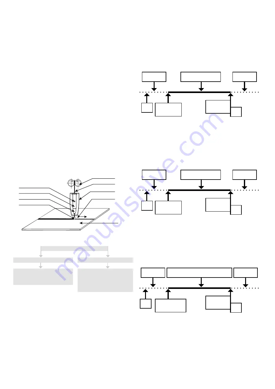
Principle of mIG/mAG welding
Welding wire is lead from the roller into the flow drawing tie with the use of
the feed. Arc joins thawing wire electrode with welding material. Welding
wire functions as a carrier of the arc and as the source of additional material
at the same time. Protective gas flows from the spacer which protects arc
and the whole weld against the effects of surrounding atmosphere (pic. 6).
Gas opening
Tip holder
Welding tip
Welding arc
Wire feeder rolls
Welding wire
Nas nosle
Protection gas
Welding
piece
Picture 6
Protection gases
Protective gases
inert gases - Mig method
Active gases - Mig method
Argon (Ar)
Helium (He)
Mixtures of He/Ar
carbon dioxide
Mixed gases
Ar/cO
2
Ar/O
2
Principle of setting welding parameters
Guidance for setting welding current and voltage MIG / MAG corresponds to
the empirical relationship U
2
= 14 + 0.05 x I2. According to this relationship,
we can determine the necessary tension. When setting the voltage, it must be
taken into account when it falls under the welding load. The voltage drop is
about 4.8 V per 100 A.
The welding current is adjusted by adjusting the required welding current
for the selected welding voltage by increasing or decreasing the wire feeding
speed, or by fine-tuning the voltage until the welding arc is stable. To achie
-
ve a good weld quality and optimum welding current setting, the distance
between the feed die and the material must be approximately 10 x Ø of the
welding wire (pic. 6). Drowning the die in the gas nozzle should not exceed
2 - 3 mm.
Welding work cycles
Welding machines work in four working cycles:
• continuous two-stroke time
• continuous four-stroke time
• spot welding two-stroke time
• pulse welding two/four -stroke time
Two-stroke cycle
Welding process is started by only the pressing the switch of the torch. The
switch must always be held during the welding process and it can be inter
-
rupted releasing the switch of the torch.
PRE-GAS
WElDING PROCESS
POST-GAS
END OF THE
WElDING
PROCESS
START OF THE
WElDING
PROCESS
1
2
1 - Push and hold the switch of torch
2 - Release the switch of torch
four-stroke cycle
It is used to weld long, when the welder does not have to hold the switch of
the torch all the time. you will start the welding process in such a way. After
releasing of the switch, the welding process still goes on. Only after a fur
-
ther pressing and releasing of the switch of the torch, the welding process
is interrupted.
PRE-GAS
WElDING PROCESS
POST-GAS
END OF THE
WElDING
PROCESS
START OF THE
WElDING
PROCESS
1-2
3-4
1-2 Push and hold the switch of torch
3-4 Release the switch of torch
Spot welding
It is used for welding by individual short spots, whose length can be con
-
tinuously adjusted for required value. by pressing the switch on the torch,
the time circuit is started, which starts the welding process and after the
set time it turns off. After further pressing the button, the whole process is
repeated.
PRE-GAS
WElDING IN ADJUSTED TIME
POST-GAS
START OF THE
WElDING
PROCESS
1
END OF
THE WElDING
PROCESS
2
1 - Push and hold the switch of torch
2 - Release the switch of torch
EN


