8-4
SE 2223/3223 Scan Engine Integration Guide
Timing Waveforms
Explanation Of The AC Symbols
Each timing symbol has five characters. The first character is always “t.” The other
characters indicate the name of the signal or the logical status of that signal. Designations
are:
a = WKUP*
b = BPR
c = Host CTS
d = PWRDWN
e = PWREN
f = float, fall time
g = trigger
h = logic level high
l = logic level low
pm = minimum voltage level
r = Host RTS
tw = time duration
v = Host RXD
w = width
x = Host TXD
Example:
tbltw = Beeper drive low time
trlcl = Time for RTS low to CTS low
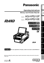
AC Test Points
Note:
AC inputs during testing are driven at V
BATT
-0.5 for logic “1” and
0.45 for logic “0.” Timing measurements are made at 0.2 V
BATT
+0.9 and 0.2 V
BATT
-0.1.
V
BATT
- 0.5
0.45 V
0.2 V
BATT
+ 0.9
0.2 V
BATT
- 0.1
Summary of Contents for SE 2223
Page 1: ...SE 2223 3223 Scan Engine Integration Guide...
Page 2: ...SE 2223 3223 Scan Engine Integration Guide 70 36636 02 Revision A January 2002...
Page 11: ...x SE 2223 3223 Scan Engine Integration Guide...
Page 29: ...1 12 SE 2223 3223 Scan Engine Integration Guide...
Page 50: ...2 21 Installation...
Page 51: ...2 22 SE 2223 3223 Scan Engine Integration Guide...
Page 61: ...3 10 SE 2223 3223 Scan Engine Integration Guide...
Page 71: ...4 10 SE 2223 3223 Scan Engine Integration Guide...
Page 203: ...9 108 SE 2223 3223 Scan Engine Integration Guide...
Page 230: ...9 135 Parameter Menus Numeric Bar Codes continued 4 5 6 7...
Page 253: ...Glossary 8 SE 2223 3223 Scan Engine Integration Guide...
Page 259: ......