


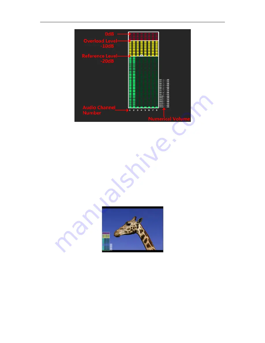
Figure 5.1-12 Audio
Level Meter
METER SELECT
item and
METER DIS MODE
item control the operational characteristics of
Audio Metering, the former controls the amount of channels displayed in a meter.
For example
: As shown in Figure 5.1-13, the meter displays at the left of the screen vertically, the
METER SELECT
is
G1+G2
, and the
METER DIS MODE
is
MODE3
, you can see the meter
displays audio channel numbers and audio values beside the meter.
There are two white horizontal level lines in the white rectangle frame of audio meter, the upper is
the
OVER LEVEL
line, and the lower is the
REFERENCE LEVEL
line. If the audio value is higher
than the reference level, the audio bar over the reference level line will display in yellow, and if the
audio value is higher than the over level, the audio bar over the
OVER LEVEL
line will display in
red, thus you could observe the exceeded part intuitively.
Figure 5.1-13 The Position of the Audio Meter On Screen
AUDIO LEVEL METER POSITION
The position of AUDIO LEVEL Meter is controlled by METER DIRECTION and METER
POSITION, the position of the audio meter on the screen could be as follows:
TOP LEFT
VERTICAL, TOP RIGHT VERTICAL, BOT LEFT VERTICAL, BOT RIGHT VERTICAL, BOTTOM
HORIZONTAL and TOP HORIZONTAL
. The illustrations of these positions are as shown in
Figure 5.1-14:


