4
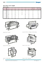
VAR
Swegon reserves the right to alter specifications.
20111011
www.swegon.com
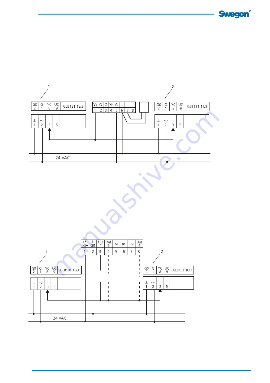
Wiring example
If the VAR is used as a constant-flow commissioning
damper, only 24 V AC current should be connected to the
controller. A number of different wiring examples with vari-
ous types of control are shown on the following pages.
˚C+C0
2
C0
2
˚C
DETECT Q 1 & 2
LMV-D3-MP SWN
NMV-D3-MP SWN
VRD3 SWN
LMV-D3-MP SWN
NMV-D3-MP SWN
VRD3 SWN
VAR
VAR
LMV-D3-MP SWN
NMV-D3-MP SWN
VRD3 SWN
LMV-D3-MP SWN
NMV-D3-MP SWN
VRD3 SWN
VAR
VAR
RTC
RTCT
Room thermostat
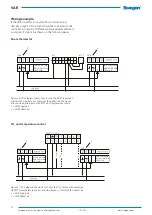
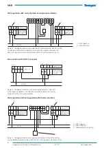
Figure 10. The diagram shows how to wire the VART room ther-
mostat with simultaneous control of the extract air. The figure
also shows an alternative with RTCT duct temperature sensor.
1 = VAR Supply air.
2 = VAR Extract air.
CO
2
and temperature control
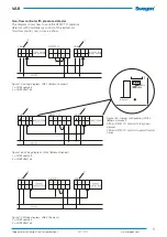
Figure 11. The diagram shows how to wire the CO
2
sensor with combined
DETECT Q temperature control and simultaneous control of the extract air.
1 = VAR Supply air.
2 = VAR Extract air.


