2
VAR
Swegon reserves the right to alter specifications.
20111011
www.swegon.com
1
2
Lengths of straight duct upstream of the VAR for
rectangular ducts
Type of obstruction
For m
2
= 5%
For m
2
= 10%
One 90° bend
3 x B
2 x B
T piece
3 x B
2 x B
Baffle-type sound attenuator
3 x t
2 x t
t = Thickness of the baffle
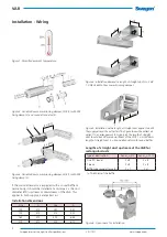
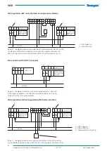
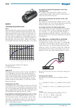
Figure 5. Installation with a length of straight duct applies to both
the supply air and the extract air. The figure shows the extract air
variant. In an arrangement for supply air, the length of straight
duct should be 500 mm downstream of the VAR. 1 = A
≥
500 mm
length of straight duct. 2 = Sound attenuator with sound baffles
Figure 4. Installation demands a length of straight duct A > 2 x B
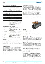
1. VAR Variable-flow commissioning damper
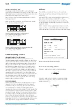
Figure 2. Variable-flow commissioning damper, VAR (1) with FSR
fixing clamp (2) and sound attenuator (3).
If the sound attenuator is equipped with a sound baffle or
centre body, it should be installed at a distance 2 x the duct
diameter (ØD) upstream or downstream of the VAR. This
applies to both supply air and extract air.
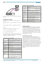
Figure 1. Permitted ambient temperature.
Installation - Wiring
Figure 3. Variable-flow commissioning damper, VAR (1) with FSR
fixing clamp (2).
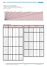
Installation dimensions
Size
A
Size
A
100
472
250
522
125
472
315
552
160
472
400
684
200
472
500
810
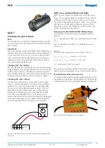
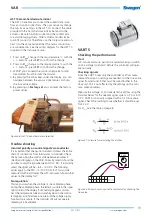
Figure 6. Open space for installation


