3
VAR
Swegon reserves the right to alter specifications.
20111011 www.swegon.com
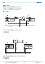
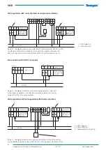
Figure 9. Wiring diagram for VAR 4.
Colour codes: 1 = Red, 2 = Black, 8 = grey, 9 = Pink
Insulate any conductors not in use.
Important!
It is important to connect system ground correctly. On
the Belimo products system ground is on wiring terminal
(conductor) 1 and on the Siemens products it is on termi-
nal (conductor) 2. For all of these, the neutral conductor
has black insulation.
U
1
2 3 5
~ Y
24V AC 0-10 alt. 2-10 V DC
MP-bus
NMV-D3-MP SWN
LMV-D3-MP SWN
a
d
b
2-10 V DC
-
+
PP
Z1 Z2
0-10 alt. 2-10 V DC
2-10 V DC
Controller configuration
VAR 1 = Belimo LMV-D3-MP SWN, NMV-D3-MP SWN
VAR 2 = Belimo VRD 3 SWN
VAR 4 = Siemens GLB181.1E/3
Electrical data
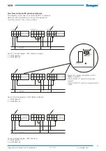
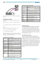
Key to Figures 7-9.
a = fully open damper
b = fully closed damper
c = preset min. airflow
d = preset max. airflow
Wiring diagrams
Figure 8. Wiring diagram for VAR 2.
Figure 7. Wiring diagram for VAR 1.
Colour codes: 1 = Black, 2 = Red, 3 and 5 = White
Insulate any conductors not in use.
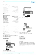
VAR 1 (Belimo compact)
Supply voltage
24 V AC ±20%, 50-60 Hz
Supply voltage
24 V DC ±10%
Controller and motor
6 VA
Input 3, resistance
100 kOhm
Input 3, control signal
0-10 alt. 2-10 V DC
Output 5, true value
2-10 V DC max. 0.6 mA
Ambient air temperature,
operation
0 °C - +50 °C
VAR 2 (Belimo Universal)
Supply voltage
24 V AC ±20%, 50-60 Hz
Supply voltage
24 V DC ±10%
Controller and motor
9.5 VA
Input 3, resistance
100 kOhm
Input 3, control signal
0-10 alt. 2-10 V DC
Output 5, true value
2-10 V DC max. 0.6 mA
Ambient air temperature,
operation
0 °C - +50 °C
VAR 4 (Siemens)
Supply voltage
24 V AC ±20%, 50-60 Hz
Controller and motor
6 VA
Input YC, resistance
100 kOhm
Input YC, control signal
0-10 V DC
Input YC if DC = -1.5 to -0.2 V closes the damper
Input YC, limitations, max.
11 V DC
Output UC, true value
0-10V DC max 1 mA
Ambient air temperature,
operation
0 °C - +50 °C


