11
VAR
Swegon reserves the right to alter specifications.
20111011 www.swegon.com
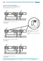
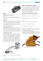
3,52 V
V DC
-
+
PP
Z1 Z2
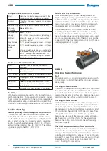
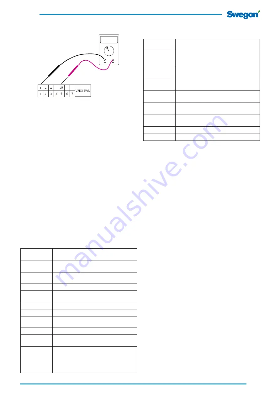
Figure 23. Shows how to connect a voltmeter for checking the
true value.
Trouble shooting
Incorrect polarity on control signal zero conductor
It is important that the neutral conductor follows the
entire chain of connections from thermostat to control-
ler. Check this by measuring the control voltage between
cables 1 and 3 on the VAR. Correctly wired it should be
possible to vary the signal between 0.5-10 V DC. If incor-
rectly wired the signal will be ~ 8 - 14 V DC; for the RTC
the signal will be ~ 2 - 8 V DC.
The airflow does not agree
This is almost always due to that the requirements for
lengths of straight ducting upstream/downstream of the
VAR have not been met. If the ducting deviates from these
requirements, the error can be as much as 20%. The flow
measurement sensor may become fouled in systems with
considerable dusty air (most often extract air systems). This
however doesn’t occur until the system has been operating
for 3-5 years. The sensor can be cleaned by blowing it with
clean air in the opposite direction, i.e. in the tube connec-
tion. We recommend compressed air in a low-pressure
aerosol tube. The duct must also be cleaned so that the
measurement flange and the pressure tappings are not
clogged.
Changing the settings
The min./max. airflow values are calculated and set as
follows:
Q
max
% required max. airflow (Q
max
) divided by nominal airflow
(Q
nom
).
Q
min
% required min. airflow (Q
min
) divided by nominal airflow
(Q
nom
).
Example:
VAR, dim. Ø160, required min./max. airflows: 51/119 l/s.
Q
max
% = Q
max
/ Q
nom
=>119/170 = 0.70 = 70%
Q
min
% = Q
min
/ Q
nom
=> 51/170 = 0.30 = 30%
Q
nom
is read from Table 1 on page 9.
Enter the settings directly in the controller. No external
instrument is needed but the settings can also be adjusted
with Belimo’s instrument, ZTH-GEN.
Configuration menu ZTH-GEN
Start:
Hold the (OK) button depressed and at the
same time connect to the VAV controller.
HW Version
SW Version
Indicates which hardware or software ver-
sion the unit runs
Reply:
"Configuration menu"appears in the display
window
Select setting
Press the
▼
button (see selection below)
Choice of
language
German
*
/English
Choice of unit
m
3
/h
*, l/s, cfm
Voltage
DC/AC 24 V (shows current supply voltage)
MP test
Shows the pulse train in the network (for
system integrator)
Expert mode
0 */ 1 (provides expanded access to settings)
Advanced
mode
0 */ 1 (provides expanded access to settings)
Exit
Via menu selection (returns automatically to
the mode for configuring the VAV controller)
or for removing the connection to the VAV
controller. The selected settings are automa-
tically stored in the ZTH.
Start menu of the VAV controller
VRD3 SWN
Indicates to which controller the ZTH-GEN is
connected.
Volume 0%
Setpoint 0%
Shows the true value in % of the nominal fl
ow Shows the calculated
set point
Volume 0%
Pressure 0Pa
Shows the true value in % of the nominal flow
Shows the manometer pressure in Pa
Volume 0%
CAV-Step
Shows the true value as a percentage of the
nominal
Auto
, Open, Close, Vmax, Vmin, Stop
Mode 0.0-10.0
-new:
Shows the current operating range for control
signalRange for control signal 0-10V or 2-10 V
Vmin
-new
Set point for min. flow in %
Set point (potentiometer in tool area)
Vmax
-new
Set point for max. flow in %
Set point (potentiometer in tool area)
Vnom
Shows nominal flow in %
p@Vnom
Shows nominal flow in Pa


