13
VAR
Swegon reserves the right to alter specifi cations.
20111011 www.swegon.com
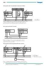
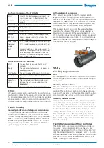
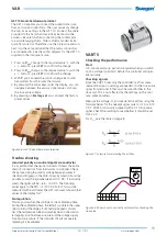
Figure 26. AST 10 hand-held micro terminal.
3,52 V
V DC
-
+
PP
Z1 Z2
VART 5
Checking the performance
Start
A 3-minute warm-up period is required when you switch
on the voltage (cold start) before the controller will oper-
ate normally.
Checking signals
Since the VART 5 uses only the controller’s airfl ow meas-
urement feature, no settings are needed. It is the true value
signal from terminal 5 that must be wired further to the
slave unit. This is not affected by the settings on the min./
max. potentiometers.
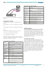
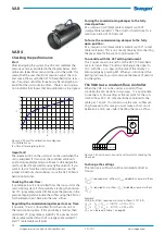
Measure the voltage, U, and calculate the airfl ow using the
formulas below for the relevant signal system; 0-10 or 2-10
V DC. VART 5 is normally supplied with a 0-10 true value
signal. Check the marking to see whether it should be set
for 2-10 V.
For Q
nom
see the table on page 8.
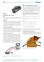
Figure 28. Shows how to connect a voltmeter for checking the
true value.
Figure 27. Formula for calculating the airfl ow
AST 10 Hand-held micro terminal
The AST 10 enables you to read the current data in air-
fl ow and control signal form. The user can easily change
the min./max. settings in the AST 10. Connect the cable
provided to the hand-held micro terminal and to the
actuator. Be careful when connecting the contact pins
to avoid damaging them. Older actuator models lack a
quick-fi t connector. Therefore use the triple wire and con-
nect it to the same terminal that the motor conductors
are connected to. See the wiring diagram for the AST 10
supplied in the instrument case.
1. Press on
V
max
change to the required value % with the
+ / - buttons - press
SET
to confi rm the change.
2. Press on
V
min
change to the required value % with the
+ / - buttons - press
SET
to confi rm the change.
3. With
Y
you can read the control voltage (set point)
transmitted from the room thermostat.
4. By pressing the arrow keys under the display, you can
navigate between the various signal values. U shows
the true value voltage.
5. By pressing on
Factory set
you can reset the factory
preset values.
Trouble shooting
Incorrect polarity on control signal zero conductor
It is important that the neutral conductor follows the entire
chain of connections from thermostat to controller. Check
this by measuring the control voltage between cables 2
(black) and 8 (grey) on the VAR. Correctly wired it should be
possible to vary the signal between 0-10 V DC. If incorrectly
wired, the signal will be ~ 6.5 - 14 V DC. The following
values apply to the RTC: ~ 3-10 V DC. N.B.! This must be
measured with a voltmeter. The AST instrument shows other
values on the display for Y.
No regulation
This may occur when the controller is in a calibration phase.
During the calibration phase, the letter S is visible in the upper
right corner of the display. If still nothing happens, discon-
nect the red pressure tube and carefully blow in the control-
ler tapping. As a fi nal measure, interrupt the voltage supply
for about one minute. If the controller still will not operate,
replacing it is inavoidable.


