ENGINE 3-7
INSTALLATION
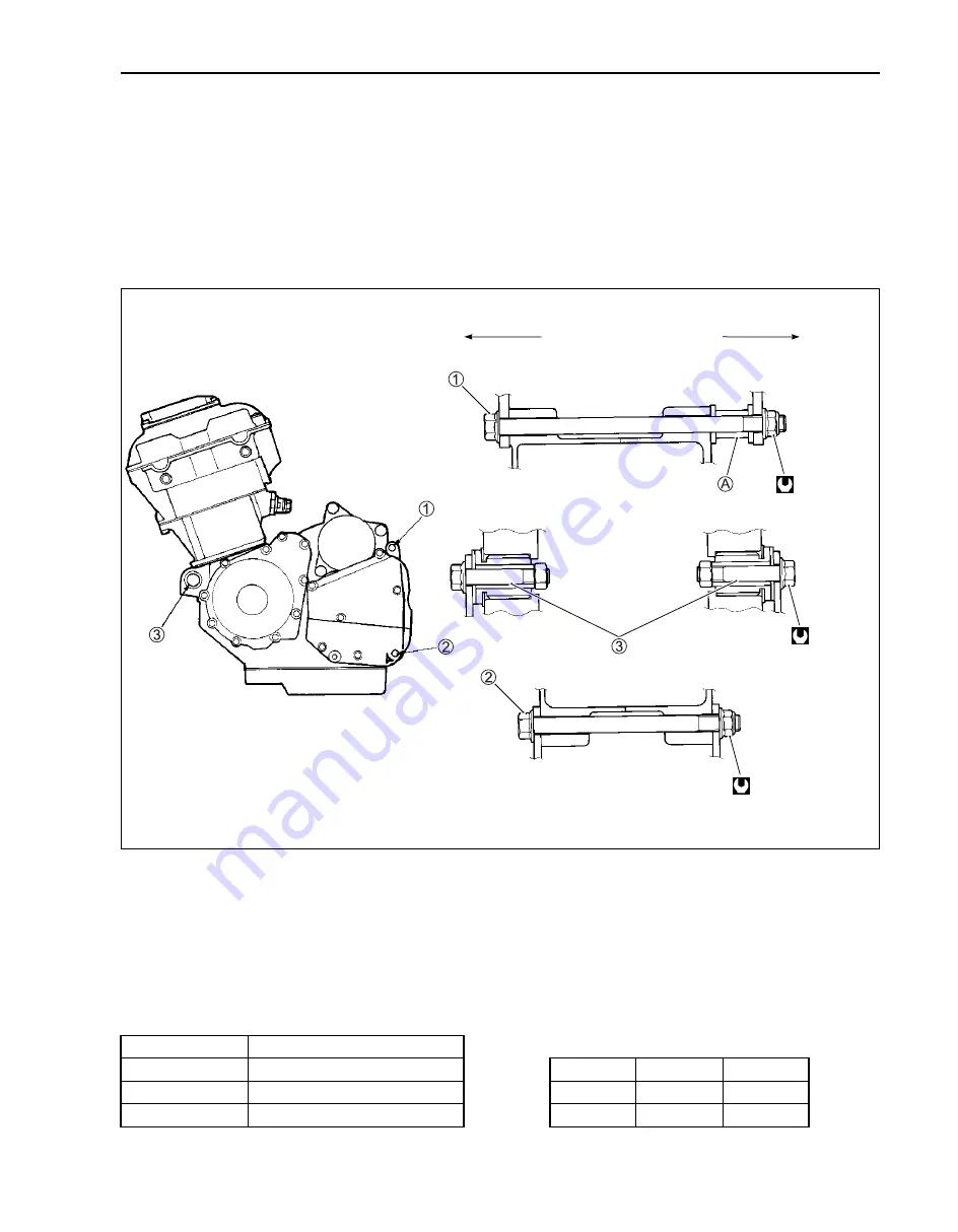
Install the engine in the reverse order of engine removal.
• Insert the two long bolts from left side. Install the brackets, spacer, bolts and nuts properly, as shown in
the following illustration.
NOTE:
The engine mounting nuts are self-locking. Once the nuts have been removed, they are no longer of any
use. Be sure to use new nuts and tighten them to the specified torque.
NOTE:
When reusing the removed engine mounting bolts (
1
and
2
), apply a small quantity of the THREAD LOCK
to their threads.
"
99000-32110: THREAD LOCK SUPER “1322”
#
Frame down tube mounting bolt: 50 N·m (5.0 kgf-m)
LENGTH
Bolt
1
180 mm
#
Bolt
2
130 mm
ITEM
N·m
kgf-m
Bolt
3
55 mm
1
,
2
75
7.5
Spacer RH
A
27 mm
3
55
5.5
LH
RH
75 N·m
(7.5 kgf-m)
55 N·m
(5.5 kgf-m)
75 N·m
(7.5 kgf-m)
Summary of Contents for GSF650
Page 1: ...GSF650 S...
Page 34: ...PERIODIC MAINTENANCE 2 21...
Page 86: ...3 50 ENGINE Remove the 2nd driven gear bushing A Remove the oil seal B...
Page 90: ...3 54 ENGINE...
Page 103: ...ENGINE 3 67 BOND 1207B should be applied to the following locations The line of BOND...
Page 130: ...3 94 ENGINE ENGINE LUBRICATION SYSTEM...
Page 132: ...3 96 ENGINE CYLINDER HEAD COOLING SYSTEM...
Page 145: ...4 10 FUEL SYSTEM I D NO LOCATION Each carburetor has an I D number 1 printed on its body...
Page 332: ...Prepared by November 2004 Part No 99500 36150 01E Printed in Japan 340...
Page 333: ...Printed in Japan K5...


