background image

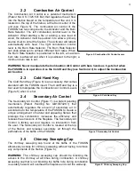
Figure 19: Liner Adaptor Installation 

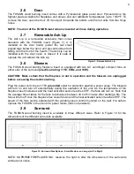
Figure 21: Location of Electric Wiring 

viii. 

Adjust  the  position  of  the  circulating  chamber  in  order  to  have  a  distance  of  10.5  inches 
from the face of the liner to the face of the existing fireplace (see Figure 20). 

ix. 

Tighten the wing nuts of the adjustable liner hole.


NOTE: If the width and/or the height of the existing fireplace is larger than the maximal width 
and/or  height  of  the  adjustable  circulating  chamber,  extend  the  width  and/or  height  of  the 
Circulating Chamber to the maximum and fill the space with Stone Wool. 

       Liner Adaptor Installation 

3.4.

a)  Insert  the  liner  adaptor  (Section  2.12)  at  the  end  of  the  liner. 

The liner must be flush with the inferior rim of the adaptor. 

b)  Tighten the clamp to secure the liner with the liner adaptor. 
c)  Secure  the  liner  adaptor  in  place  with  the  sheet  metal  screw 

provided. 


       Firebox Installation 

3.5.

a)  Slide the FUSION firebox into the circulating chamber. 
b)  Align the liner adaptor with the flue of the insert (see Figure 19). 
c)  Insert your hand in the chimney sweeping cap opening and pull 

the liner down by its handle. 

d)  Use  your  thumb  to  bend  the  4  tabs  of  the  liner  adaptor 

outward to secure the liner in place. 

e)  Reposition  the  chimney  sweeping  cap  back  in  the 

chimney sweeping cap hole of the baffle. 


WARNING: The chimney sweeping cap should be blocking 
the access to the chimney at all times during combustion. 
A  chimney  sweeping  cap  that  is  not  blocking  the  baffle 
hole  during  combustion  is  a  safety  hazard,  will  overheat 
the fireplace and void the warranty. 

       Power Cord Side Reversal 

3.6.

The blowers of the FUSION insert are factory installed and the 
power cord is located at the left side of the surround when 
facing it (see Figure 21). However, the power cord location can 
be switched to the right side by following the below instructions: 

a)  Unfold the cover that secures the power cord in place. 
b)  Loosen the nut of the strain relief. 
c)  Bring the power cord to the opposite side and secure the 

strain relief by tightening the nut. 

d)  Bend the cover to its original position. 


Figure 20: Fusion Installation


Summary of Contents for FUSION 24

Page 1: ...hase II particulate emission standards from the Environmental Protection Agency OWNER S MANUAL INSTALLATION OPERATION Important Keep the owner s manual for future use This product is proudly manufactu...

Page 2: ...r Installation 7 3 2 Liner Installation 7 3 3 Adjustable Circulation Chamber 7 3 3 1 Assembly 7 3 3 2 Installation 7 3 4 Liner Adaptor Installation 8 3 5 Firebox Installation 8 3 6 Power Cord Side Rev...
Page 3: ...ney Maintenance 16 6 3 Cleaning of Glass 17 6 4 Replacement of Gasket 17 6 5 Replacement of Glass 17 6 6 Door Latch Lubrication 18 6 7 Paint 18 6 8 Removal of Firebox 18 6 9 Replacement Parts 19 7 WAR...

Page 4: ...operation keep children pets flammable liquids or combustible materials at a safe distance Ensure that all clearances to combustible materials are respected Contact with the unit during operation may...

Page 5: ...Figure 1 FUSION Firebox Figure 2 Dimensions of FUSION Firebox Figure 3 Dimensions of FUSION Figure 4 Dimensions of FUSION with Circulating Chamber 2 COMPONENTS 2 1 Overall Dimensions 2...

Page 6: ...d Key The Cold Hand Key Figure 6 is an accessory that comes standard with the FUSION insert The Cold Hand Key is a tool used to manipulate the Combustion Air Control Levers Figure 5 when it is hot 2 4...

Page 7: ...surround electrical rating 115V 60Hz and 19W CAUTION Make certain that the fireplace in not in operation and the blowers are unplugged before accessing the electrical wiring Plug the power cord into a...

Page 8: ...The FUSION Liner Adaptor is a component that comes with the FUSION and is required to connect the stainless steel liner to the FUSION insert Figure 13 2 13 Metal Tag The Metal Tag is found on the fron...

Page 9: ...re starting the installation Failure to follow these instructions may result in property damage bodily harm and even death Modifications of the instructions presented in this section without written a...

Page 10: ...Stone Wool insulation to prevent heat from escaping Adjustable Circulating Chamber 3 3 3 3 1 Assembly i Remove the front cover of the unit and cut along the perforated lines to later use as the bottom...

Page 11: ...n the liner adaptor with the flue of the insert see Figure 19 c Insert your hand in the chimney sweeping cap opening and pull the liner down by its handle d Use your thumb to bend the 4 tabs of the li...

Page 12: ...a full length stainless steel liner flexible or rigid that meets 2100 F or 1149 C HT requirements in UL 1777 or ULC S635 Canada The liner must be properly installed to the flue collar and the chimney...

Page 13: ...stible wall is recessed the depth of the mantle can be increased by the amount of the recess Note that a mantel cannot be installed below the minimum clearance of 36 75 from the bottom of the mantel t...

Page 14: ...NG Do not keep the door open while the fireplace insert is in operation 4 2 First Fires Due to oil residues and the curing of the paint of the fireplace insert it is normal to smell an odor for the fi...

Page 15: ...estarter is well lit close the door Do not leave the door open for more than 2 minutes CAUTION The wood should be placed away from the door to avoid damage to the glass WARNINGS Over firing the unit m...

Page 16: ...or of the FUSION slightly unlatched until you see a flame in the firebox Never leave the FUSION door unlatched without constant supervision f Completely latch the FUSION door Assure that a flame is ma...

Page 17: ...tically in the presence and absence of heat respectively NOTE Standard location of the power cord is on the left when facing the surround but can be switched to the opposite side Please see Section 3...

Page 18: ...he FUSION Heat the chimney by burning newspaper near the exhaust of the baffle system Over Firing 5 2 The appearance of a red glow on the exterior of the firebox top and sides and or on the flexible l...

Page 19: ...lue lining When ignited this creosote makes an extremely hot fire The chimney connector and chimney burning wood or coal should be inspected at least once every two months during the heating season to...

Page 20: ...t for the FUSION gasket b Remove the door from the firebox and place it face down on a soft surface NOTE Rotate the handle to permit proper placing c Cover all painted surfaces of the door to avoid da...

Page 21: ...If applying paint to the door properly cover mask the glass of the door using painters tape and cardboard Wait for paint to dry before operating the unit Refer to the instructions on the label of the...

Page 22: ...raphite coated square gasket 0 1875 thick 7 length GSK_25_7 Graphite coated square gasket 0 25 thick 7 length RG 125 19 06 AC centrifugal compact fan Electrical rating 115VAC 60Hz 19W Certification VD...

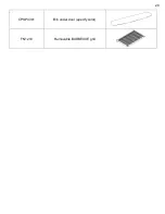
Page 23: ...CPSP0301 Bib under door specify color FN1210 Removable BARBECUE grill 20...

Page 24: ...UPREME FIREPLACES INC will provide replacement parts if available at no charge except for the parts mentioned in the EXCLUSIONS portion of this warranty Supreme Fireplaces Inc shall not be responsible...

Page 25: ...rranty by refunding the wholesale price of the defective part s The manufacturer shall in no event be responsible for any consequential damages of any nature which are in excess of the original purcha...

Reviews: