


SC512 Chassis Manual
A-4
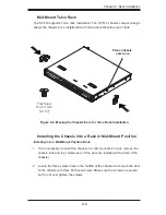
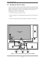
A-3 Routing the Chassis Cables
In order for the SC512 chassis to perform safely and efficiently, it is important that the
cables are routed correctly. Follow the instructions below and review both the cabling
diagram and photograph to ensure that the cabling has been properly routed.
Preparing the Chassis for Cable Routing
Unplug the chassis from any power source.
1.
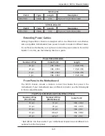
Review the diagram on the following page, taking note of the naming of each
2.
cable.
Remove the screws securing the fan platform to the bottom of the chassis.
3.
RIGHT MIDDLE BRACKET
MIDDLE BRACKET
FAN
PWR
SATA PWR
(RIGHT ANGLE)
SATA PWR
(RIGHT ANGLE)
SATA
(STRAIGHT)
HDD
HDD
LEFT
SATA
(RIGHT ANGLE)
MB SATA
PORTS
MOTHERBOARD
AREA
1
1
1A
1
2A
1
3A
1
4A
1
5A
1
3C
1
3B
1
2B
1
2C
1
1C
1B
Figure A-1: Chassis Cable Routing Diagram (SC512L-200/260)
Summary of Contents for SC512C-260 Series
Page 8: ...SC512 Chassis Manual viii Notes...
Page 24: ...SC512 Chassis Manual 3 8 Notes...
Page 28: ...SC512 Chassis Manual 4 4 Notes...
Page 44: ...SC512 Chassis Manual 5 16 Notes...
Page 62: ...SC512 Chassis Manual A 8 Notes...
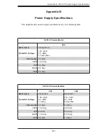
Page 65: ...B 3 Appendix B SC512F Power Supply Specifications Notes...