


4-1
Chapter 4: System Interface
Chapter 4
System Interface
4-1 Overview
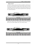
There are several LEDs on the control panel and on the drive carriers to keep you
constantly informed of the overall status of the system, as well as the activity and
health of specific components. Most SC512 models are two buttons on the chassis
a control panel: a reset button and an on/off switch. This chapter explains the mean-
ings of all LED indicators and the appropriate response you may need to take.
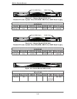
Figure 4-1: Chassis LED and Buttons
Summary of Contents for SC512C-260 Series
Page 8: ...SC512 Chassis Manual viii Notes...
Page 24: ...SC512 Chassis Manual 3 8 Notes...
Page 28: ...SC512 Chassis Manual 4 4 Notes...
Page 44: ...SC512 Chassis Manual 5 16 Notes...
Page 62: ...SC512 Chassis Manual A 8 Notes...
Page 65: ...B 3 Appendix B SC512F Power Supply Specifications Notes...