background image

3-5

Chapter 3: Chassis Components

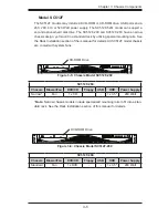
Model SC512F

The SC512F models may include a DVD-ROM or CD-ROM drive, USB ports and a 
260, 280, 410 or 520 Watt power supply. The SC512F-520L model can support a 
second optional hard disk drive. The SC512F-200 and SC512F-260 have a narrow 
chassis design, yet mount in a standard rack by utilizing special mounting rails. See 
the Rack Installation section of theis manual for details. All SC512F model chassis 
are cooled with system fans.

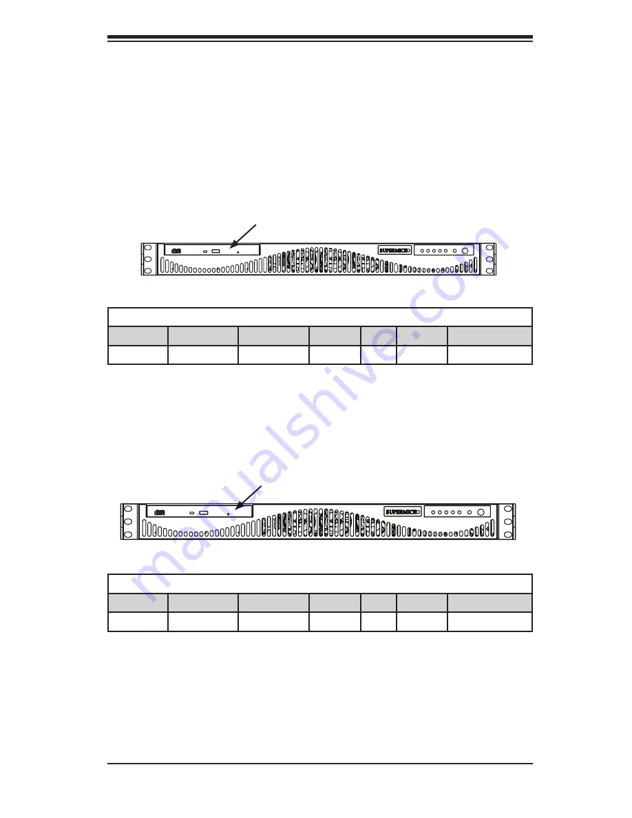
Figure 3-5: Chassis Model SC512F-260

CD-ROM Drive

SC512F-260

Chassis Blower/Fan

DVD/CD

Floppy USB

HDD

Power Supply

Narrow*

Fan

1x CD

-

-

1x 3.5"

260 Watt

Note:

 Narrow chassis models include specialized mounting rails to fit into a stan

-

dard rack. See the Rack Installation section of this manual for details.

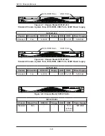
DVD-ROM Drive

Figure 3-6: Chassis Model SC512F-280

SC512F-280

Chassis Blower/Fan

DVD/CD

Floppy USB

HDD

Power Supply

Standard

Fan

1x DVD

-

-

1x 3.5"

280 Watt

Summary of Contents for SC512C-260 Series

Page 1: ...SC512 CHASSIS Series USER S MANUAL 1 0a SC512 200B SC512C 260 B SC512F 280 B SC512F 520 B SC512L 260 B SC512F 520L B SC512L 260 B LCD SC512F 410 B SC512L 200B SC512F 260 B SUPER...

Page 2: ...D OR USED WITH THE PRODUCT INCLUDING THE COSTS OF REPAIRING REPLACING INTEGRATING INSTALLING OR RECOVERING SUCH HARDWARE SOFTWARE OR DATA Any disputes arising between manufacturer and customer shall b...

Page 3: ...rmicro s SC512 1U chassis features a unique and highly optimized design for dual core Xeon platforms The chassis is equipped with a 200 260 280 410 or 520 Watt high efficiency power supply for superb...

Page 4: ...chassis model including the fans bays airflow shields and other components Chapter 4 System Interface Refer to this chapter for details on the system interface which includes the functions and informa...

Page 5: ...ystem Safety 2 1 Overview 2 1 2 2 Warnings and Precautions 2 1 2 3 Preparing for Setup 2 1 2 4 Electrical Safety Precautions 2 1 2 5 General Safety Precautions 2 2 2 6 System Safety 2 3 Chapter 3 Chas...

Page 6: ...Slot Setup 5 8 5 7 Installing the Air Shroud 5 9 Installation Complete 5 10 5 8 System Fans 5 11 System Fan Tray 5 11 System Fan Tray Replacement 5 12 5 9 Power Supply 5 13 Power Supply Failure 5 13 R...

Page 7: ...nstalling the Outer Rails to the Rack 6 6 Installing the Chassis into a Rack 6 8 Mid Mount Telco Rack 6 9 Installing the Chassis into a Rack in Mid Mount Position 6 9 Appendix A Cables Screws and Othe...

Page 8: ...SC512 Chassis Manual viii Notes...

Page 9: ...mbers for your par ticular chassis model http www supermicro com products chassis 1U chs 512 Chapter 1 Introduction 1 1 SC512 Chassis Model CPU HDD I O Slots Power Supply SC512 200B UP 1x Fixed FH 200...

Page 10: ...board specifications pages on our web site for updates on supported processors I O Expansion slots Each version of the SC512 chassis includes one full I O expansion slot Peripheral Drives Some SC512 c...

Page 11: ...dress Super Micro Computer B V Het Sterrenbeeld 28 5215 ML s Hertogenbosch The Netherlands Tel 31 0 73 6400390 Fax 31 0 73 6416525 Email sales supermicro nl General Information support supermicro nl T...

Page 12: ...ust be mailed when service is complete For faster service RMA authorizations may be requested online http www supermicro com support rma Whenever possible repack the chassis in the original Supermicro...

Page 13: ...a clean dust free area that is well venilated Avoid areas where heat electrical noise and eletromagnetic fields are generated You will also need it placed near at least one grounded power outlet When...

Page 14: ...ck Use extreme caution when using metal tools which can easily damage any electrical components or circuit boards they come into contact with Do not use mats designed to decrease electrostatic dischar...

Page 15: ...p and secure it to the rack unit with the retention screws after ensuring that all connections have been made 2 6 System Safety Electrostatic discharge ESD is generated by two objects with different e...

Page 16: ...s only do not touch its components peripheral chips memory modules or contacts When handling chips or modules avoid touching their pins Put the serverboard and peripherals back into their antistatic b...

Page 17: ...oppy drive and or two USB ports For the latest shipping lists visit our Web site at http www supermicro com Fans The SC512 model chassis accepts two or three system fans powered by the moth erboard Th...

Page 18: ...rs A list of Supermicro Authorized Distributors System Integrators Reseller can be found at http www supermicro com Click the Where to Buy link 3 4 Chassis Model Options The following section lists th...

Page 19: ...r 3 Chassis Components Figure 3 1 Blower Cooled Chassis Model Air blower unit included in chassis models SC512 SC512C and SC512L Figure 3 2 Fan Cooled Chassis Model System fans included in chassis mod...

Page 20: ...ppy drive USB ports and a 200 or 260 Watt power supply The SC512C model chassis is cooled with an internal blower unit Figure 3 4 Chassis Model SC512C Floppy Drive CD ROM Drive USB Ports SC512 200 Cha...

Page 21: ...ack Installation section of theis manual for details All SC512F model chassis are cooled with system fans Figure 3 5 Chassis Model SC512F 260 CD ROM Drive SC512F 260 Chassis Blower Fan DVD CD Floppy U...

Page 22: ...wer Supply USB Ports USB Ports Figure 3 9 Chassis Model SC512F 520L DVD ROM Drive DVD ROM Drive SC512F 520 Chassis Blower Fan DVD CD Floppy USB HDD Power Supply Standard Fan 1x DVD USB 1x 3 5 520 Watt...

Page 23: ...re 3 10 Chassis Model SC512L SC512L Chassis Blower Fan DVD CD Floppy USB HDD Power Supply Standard Blower 2x 3 5 200 Watt SC512L 260 Chassis Blower Fan DVD CD Floppy USB HDD Power Supply Standard Blow...

Page 24: ...SC512 Chassis Manual 3 8 Notes...

Page 25: ...nstantly informed of the overall status of the system as well as the activity and health of specific components Most SC512 models are two buttons on the chassis a control panel a reset button and an o...

Page 26: ...s has five LEDs These LEDs provide you with critical information related to different parts of the system This section explains what each LED indicates when illuminated and any corrective action you m...

Page 27: ...cates network activity on GLAN1 when flashing HDD Indicates IDE channel activity SAS SATA drive SCSI drive and or DVD ROM drive activity when flashing Power Indicates power is being supplied to the sy...

Page 28: ...SC512 Chassis Manual 4 4 Notes...

Page 29: ...Removing the Chassis Cover Installing the Hard Drive Installing the Motherboard includes I O Shield and Expansion Card Slot setup Installing the DVD or CD ROM Drive Installing the Air Shroud General...

Page 30: ...1 Removing the Chassis Cover Warning Except for short periods of time do NOT operate the server without the cover in place The chassis cover must be in place to allow proper airflow and prevent overh...

Page 31: ...ed at the end of this chapter 3 Remove the CD ROM drive To do this remove the two screws holding the drive in place One screw is external The other is internal Figure 5 2 Removing the CD ROM Drive to...

Page 32: ...ort a second hard drive Insert the second hard drive at this time If you are are not using the models listed above skip this step Flat head M4 x 4 mm 0 157 RAIL Round head M4 x 4 mm 0 157 Flat head M5...

Page 33: ...heatsinks to lower the temperature of the components Heatsinks for the SC512 chassis must be rated for 1U or less Figure 5 5 The SC512 Backplate I O Shield 5 5 Installing the Motherboard Flat head M4...

Page 34: ...ssis standoffs and carefully place the 3 motherboard in the chassis Make sure rear ports line up with the I O shield Secure the motherboard to the chassis using the ten rounded Phillips head 4 screws...

Page 35: ...wo screws One screw is external The other screw is internal Figure 5 7 Replace the DVD ROM CD ROM Drive Replace these screws DVD ROM CD ROM Drive Hard Drive Round head M4 x 4 mm 0 157 Flat head M5 x 1...

Page 36: ...the Expansion Card Installing Add on and Expansion Cards 1 Disconnect the power supply lay the chassis on a flat surface and open the chassis cover 2 Slide the add on card clip upward 3 Slide the add...

Page 37: ...ug fit Perforated Tabs The air shroud helps cool the chassis by directing heated air through the rear of the chassis When installing the air fan be aware of the following The air shroud is designed to...

Page 38: ...ow through the chassis Pull all excess cabling out of the airflow path or use shorter cables The control panel LEDs inform you of system status See Chapter 3 System Interface for details on the LEDs a...

Page 39: ...re The SC512F 280 chassis accepts two fans instead of three 5 8 System Fans System Fan Tray Systems fan trays are components that house groups of fans The system fan tray is held in place by two rivet...

Page 40: ...fans to the motherboard 7 Replacing Individual System Fans Fans can be replaced individually without removing the system fan tray There is no need to power down the system when replacing a system fan...

Page 41: ...An amber light will be illuminated on the power supply when the power is off An illuminated green light indicates that the power supply is operating Power Supply Failure The SC512 series chassis has o...

Page 42: ...out of the chassis 5 Place the new power supply into the chassis and secure the power supply 6 using the three screws and internal brace Connect the power supply to the motherboard and other chassis c...

Page 43: ...LED Panel Power down and unplug the system 1 Remove the chassis cover 2 Disconnect the cord to the front panel 3 Locate and remove three screws holding the panel in place If your chassis 4 supports d...

Page 44: ...SC512 Chassis Manual 5 16 Notes...

Page 45: ...noise and electromagnetic fields are generated You will also need it placed near a grounded power outlet Be sure to read the Rack and Server Pre cautions in the next section 6 3 Preparing for Setup T...

Page 46: ...two or more si multaneously may cause the rack to become unstable General Server Precautions Review the electrical and general safety precautions that came with the com ponents you are adding to your...

Page 47: ...at the amount of airflow required for safe operation is not compromised Mechanical Loading Equipment should be mounted into a rack so that a hazardous condition does not arise due to uneven mechanical...

Page 48: ...he SC512F 280 and SC512F 520 chassis models are designed with a narrower chassis Specialized rails are included to mount the chassis to a standard rack Identifying the Sections of the Rack Rails Optio...

Page 49: ...n 4 Installing the Inner Rail Extension The SC512F includes chassis ears that you must remove before installing the rails Removing the Chassis Ears Locate and remove the three screws holding the chass...

Page 50: ...gly into the rack Secure the long bracket to the front side of the outer rail with two M5 screws 3 and the short bracket to the rear side of the outer rail with three M5 screws Use a washer with each...

Page 51: ...6 7 Chapter 6 Rack Installation SCALE 0 380 Figure 6 4 Installing the Outer Rails to the Server Rack 3 3 2...

Page 52: ...alled on the rack Align chassis rails with the front of the rack rails 2 Slide the chassis rails into the rack rails keeping the pressure even on both 3 sides you may have to depress the locking tabs...

Page 53: ...cate the three screw holes in the middle of the chassis and secure the ears 2 to the chassis with three flat head screws Make sure the screws are secure but do not over tighten the screws Figure 6 6 M...

Page 54: ...screw the chassis to the rack using the 3 three screw holes located in the chassis ears The chassis is held in place by the chassis ears and does not slide in and out 4 of place Round head M4 x 4 mm 0...

Page 55: ...our Web site at www supermicro com A 2 Cables Included with SC512 Chassis SC512C 260 Part Type Length Description CBL 0049 Cable 9 cm 16 pin to 16 pin ribbon cable SC512C Part Type Length Description...

Page 56: ...able 40 cm 16 pin to 16 pin FP Cable Lead Free Cable 6 Regional power cord SC512F 520 Part Type Length Description CBL 0142L Cable 30 cm 12 Seven pin SATA with two 90 degree side connectors Lead free...

Page 57: ...the Motherboard The SC512 chassis includes a cable to connect the chassis front panel to the motherboard If your motherboard uses a different connector use the following list to find a compatible cabl...

Page 58: ...paring the Chassis for Cable Routing Unplug the chassis from any power source 1 Review the diagram on the following page taking note of the naming of each 2 cable Remove the screws securing the fan pl...

Page 59: ...d over the top of hard drive 2 2B Route cable 2A through the left middle bracket 3 Plug cable 2A into lower SATA port 2C on the motherboard 4 Routing Split Cable 3A 4A from Hard Drives 1B 2B to the Po...

Page 60: ...A 6 Figure A 2 Chassis Cable Routing Checking the Cable Routing Check the cable routing by following out each cable in the previous steps and 1 comparing them to the diagram in Figure A 1 and the phot...

Page 61: ...arts listed Flat head M4 x 4 mm 0 157 RAIL Round head M4 x 4 mm 0 157 Flat head M5 x 12 mm 0 472 Washer for M5 DVD ROM CD ROM FLOPPY DRIVE Flat head 6 32 x 5 mm 0 197 Pan head 6 32 x 5 mm 0 197 Round...

Page 62: ...SC512 Chassis Manual A 8 Notes...

Page 63: ...dels 200 260 MFR Part PWS 0043 PWS 0055 Rated AC Voltage 100 240V 60 50Hz 5 3 Amp 100 240V 60 50Hz 4 Amp Max 5V standby 2 0 Amp 2 0 Amp 12V 12 0 Amp 18 0 Amp 5V 20 Amp 25 0 Amp 3 3V 17 0 Amp 15 0 Amp...

Page 64: ...mp 15 0 Amp 15 Amp 12V 0 5 Amp 1 0 Amp 1 Amp SC512F 410 Chassis Model 200 MFR Part PWS 0061 DC Voltage Voltage Range 36V to 72V Nominal Voltage 48V Max Input Current 18A 48V DC Output 5V 3 3V 180W 5V...

Page 65: ...B 3 Appendix B SC512F Power Supply Specifications Notes...

Page 66: ...reasonably expected to result in significant injury or loss of life or catastrophic property damage Accordingly Supermicro disclaims any and all liability and should buyer use or sell such products fo...

Reviews: