5-22
S
uper
W
orkstation 5037A-I User's Manual
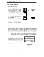
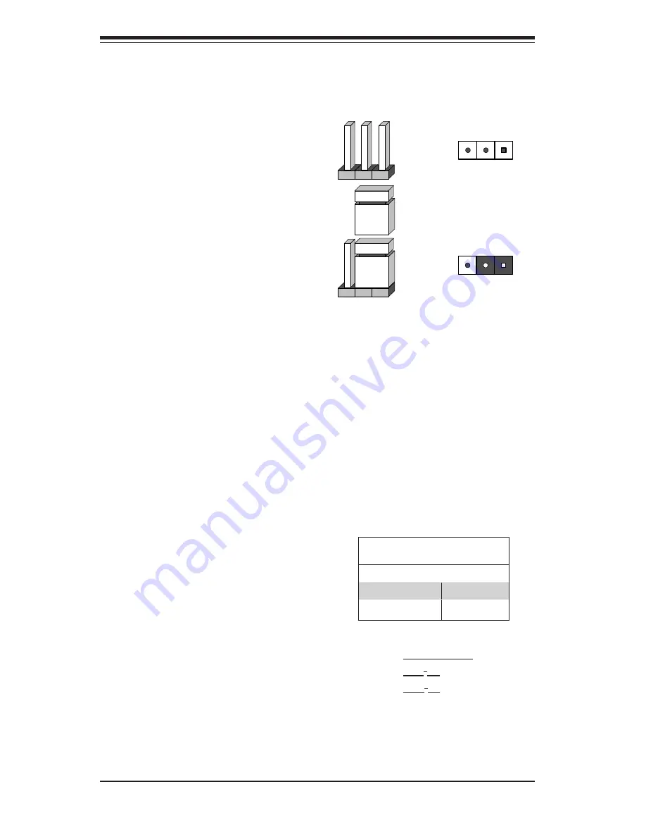
5-10 Jumper Settings
Explanation of Jumpers
To modify the operation of the mother-
board, jumpers can be used to choose
between optional settings. Jumpers
create shorts between two pins to
change the function of the connector.
Pin 1 is identified with a square solder
pad on the printed circuit board. See
the motherboard layout pages for
jumper locations.
Note:
On a two-pin jumper, "Closed"
means the jumper is on both pins and
"Open" means the jumper is either on
only one pin or completely removed.
Connector
Pins
Jumper
Setting
3 2 1
3 2 1
Clear CMOS (JBT1)
JBT1 is used to clear CMOS. Instead of pins, this "jumper" consists of contact pads
to prevent accidental clearing of CMOS. To clear CMOS, use a metal object such
as a small screwdriver to touch both pads at the same time to short the connec-
tion. Always remove the AC power cord from the system before clearing CMOS.
Note:
For an ATX power supply, you must completely shut down the
system, remove the AC power cord and then short JBT1 to clear CMOS.
A. Clear CMOS
B. JI
2
C1
C. JI
2
C2
PCI Slot SMB Enable
Jumper Settings
Jumper Setting Definition
Short (Default)
Enabled
Open
Disabled
PCI Slot SMB Enable (J
I
2
C1/JI
2
C2)
Use Jumpers I
2
C1/I
2
C2 to enable PCI
SMB (System Management Bus) support
to improve system management for the
PCI slots. See the table on the right for
jumper settings.
Summary of Contents for 5037A-I
Page 1: ...SuperWorkstation 5037A I SUPER USER S MANUAL 1 0...
Page 5: ...v Preface Notes...
Page 14: ...SuperWorkstation 5037A I User s Manual 1 6 Notes...
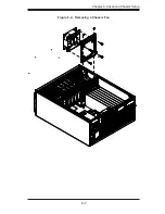
Page 59: ...Chapter 6 Advanced Chassis Setup 6 7 Figure 6 4 Removing a Chassis Fan...
Page 66: ...6 14 SuperWorkstation 5037A I User s Manual Notes...
Page 92: ...7 26 SuperWorkstation 5037A I User s Manual Notes...
Page 94: ...A 2 SuperWorkstation 5037A I User s Manual Notes...

