Premier VS Infrared Heating System
Page 66
June 04, 2014
COMMISSIONING
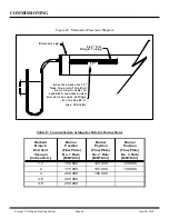
(s e e T a b le B )
e n d v e n t v a c u u m s e ttin g s
e s ta b lis h re c o m m e n d e d
V e n t C a p in o rd e r to
fro m th e e n d o f th e E n d
In s e rt m a n o m e te r 1 2 "
H
E n d v e n t c a p
1 2 "
0 .2 5 " O .D .
R id g id T u b in g
H = In c h e s W .C .
Figure 48: Manometer Placement Diagram
Radiant
Branch
End Vent
Vacuum
[Inches W.C.]
Burner
Position
(Flow Plate)
No. 1 Rate
[MBTU/hr]
Burner
Position
(Flow Plate)
No. 2 Rate
[MBTU/hr]
Burner
Position
(Flow Plate)
No. 3 Rate
[MBTU/hr]
1.7
150 000
120 000
120 000
2
175 000
130 000
130 000
3
200 000
165 000
3.6
225 000
4.5
250 000
Table E: Vacuum System Settings for Relative Burner Rates


