31
6) Adjusting Parts related to Trimming
A. Structure of Trimming device
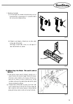
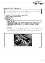
The Trimming Structure of the machine is shown in the following figure38.
[Caution]
This machine adopts trimming gear pattern in which gear source is the cam in the lower shaft. Therefore, at the time of
adjusting the machine, if the sewing machine is rotated with the trimming solenoid running, there will be damage on both
movable knife and needle caused by the collision of them. When operating the machine with solenoid running, make sure
to operate within the regular trimming length (from lower part to upper part of needle bar).
[ Fig. 38 ]
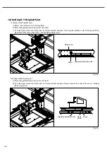
[ Fig. 40 ]
C. Adjusting movable knife position
a) Adjusting movable knife position
As in the Figure 40, standard position of movable knife is
referred to the point when slot of trimming holder is
aligned with carved point on the upper part of bed.
B. Adjusting trimming cam
a) Standard position of trimming cam
③
is referred to the
point when trimming cam
③
contacts trimming cam
roller
⑤
, movable knife is at its standard position, and
carved point
①
of the machine meets yellow carved point
②
on the pulley.
b) Unfasten trimming cam clamp screw
④
to place
trimming cam at its standard position.
c) After adjustment, fasten trimming cam clamp screw
④
firmly.
[ Fig. 39 ]
⑤
④
③
①
②


