30
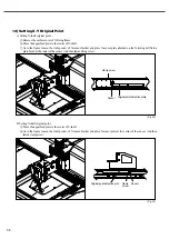
[Fig. 35]
[Fig. 36]
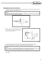
G. Adjustment of Presser Foot Stroke(Adjustment of Presser
Foot UP/DOWN Motion) After unfastening stud screw
①
of presser foot adjusting arm, placing it to A direction,
presser foot stroke increases. Placing to direction B,
stroke decreases.(It is set to 4mm at the moment of
factory shipping).
B A
③
4mm
④
②
→
→
①
Presser Foot
Adjusting Arm
Presser Bar Bush
Presser Bar
Holder
F. Check the tightening status of screws, and adjust the presser foot
’
s stroke.
[Cautions]
If there is no interval between Presser Bar Holder and Presser Bushing, the machine may be interfered during its
operation. If the handle is completely tightened, the machine may be damaged during its operation.
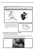
5) Adjusting thread release and dish opening width
ⓐ
Unfasten the thread release air cylinder bracket clamp screw
①
.
ⓑ
Operate a trimming to open and widen the thread guide dish.
ⓒ
Adjust the opening of the thread guide dish to be 0.6 ~ 0.8mm wide for general materials, and 0.8 ~ 1mm for heavy materials.
ⓓ
The closer the thread release air cylinder is to the needle bar, the wider the opening of thread guide dish becomes; and the closer
the thread release air cylinder is to the upper shaft motor, the narrower the opening becomes.
ⓔ
After adjusting the opening of the dish, fasten the clamp screw with the cylinder operating smoothly.
[ Fig. 37 ]
The opening
becomes wide
①
The opening
becomes narrow
①


