background image


Serial Flash Programmer[S550-SFWv3] Operation Manual


86


7.1.3.


Initialization 


You  can  initialize  data  that  is  stored  in  the  S550-SFWv3  internal  memory  on  unit  basis  for  security  purposes. 
The followings are the procedures for initialization. 

*For initialized settings (factory settings), see “9.6 Initialized Settings (factory setting) List”. 
*Initialization takes 1 to 2 minutes. 


Connect PC and S550-SFWv3 main unit with USB. 

・ 

For the connection when initializing, see “4.1 Connection for Downloading / Uploading / Initializing”. 


Confirm S550-SFWv3 start up 

・ 

The start up is complete when the “USB” LED is lit after, “Power” LED on, “Pass”, “ID Err”, “Fail” LEDs 
are lit in order one time each then the buzzer sounds. 


*If the “Pass” and “ID Err” LEDs are lit and the lower 1byte of the user program checksum is displayed on the center display after the 
buzzer sound, the programming data has been downloaded to the S550-SFWv3. 


Start Initializing 

・ 

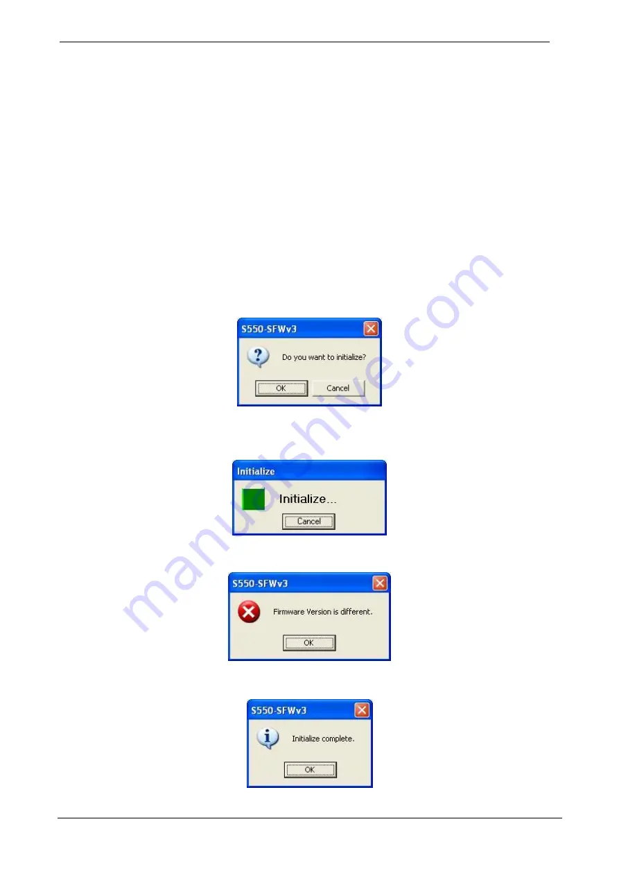
Click the “Initialize” button and the confirmation dialog asking, 

“Do you want to initialize?”

 Click the “OK” 

button to start initializing. 


・ 

The progress bar will show the initializing progress status. 
Click “Cancel” to cancel initializing in midstream. 

*If cancelled, data to program is deleted partially, and programming and uploading cannot be executed. 

・ 

All LEDs turns off and center display turns off when initialization is started.   


*If the firmware version of the S550-SFWv3 is different, initializing will not be processed with the message “

Firmware Version 

is different

”. 


Initializing complete 

・ 

When a message “

Initialize Complete

” appears, initializing is complete.   

・ 

”_”,”_” is displayed on the center display when initializing is complete.     


Summary of Contents for S550-SFWv3

Page 1: ...Serial Flash Programmer S550 SFWv3 Operation Manual Sunny Giken Inc 2 0 1 2 0 1 ...

Page 2: ... by using this product and or the software attached to this product claimed by users and or any intermediaries Specifications of this product and or the software attached to this product may be modified without notice for improvement The names of systems products and or services used in this manual are either registered trademarks or trademarks of each manufacturer The captions of the TM and R are...

Page 3: ...river 29 5 2 Uninstalling 30 5 2 1 Uninstalling Control Software 30 5 2 2 Uninstalling USB Driver 31 6 Control Software 34 6 1 Main Screen 34 6 1 1 Main Screen 34 6 1 2 About Screen 38 6 1 3 Initialize Setting Screen 39 6 1 4 UpLoad Setting Screen 40 6 1 5 DownLoad Setting Screen 41 6 1 6 Program Setting Screen 42 6 2 Device Setting Screen 43 6 2 1 Device Setting Screen 43 6 2 2 Device Detail Disp...

Page 4: ...r Information Display 107 8 3 6 Data Switch Display 108 9 Messages and Warnings 109 9 1 Message Dialogs 109 9 2 Buzzer Sound List 112 9 3 LED Status List 113 9 4 List of Center Display 114 9 5 List of Error Information on Center Display 115 9 6 Execution Detail Screen List 115 9 7 Initialized Settings factory setting List 116 10 Troubleshooting 117 10 1 Mode entry error occurs when programming 117...

Page 5: ...aces Places where there is the presence of corrosive gases Places exposed to direct sunlight Places surrounded by equipments that could become sources of noises Places with severe mechanical shock and or constant mechanical vibration Operational ambient temperature 0 C to 40 C Humidity below 80 non condensing Preventing electrostatic buildup for handling this product and devices is highly recommen...

Page 6: ...ation of the Serial Flash Programmer S550 SFWv3 is illustrated below For details on connection according to functions see 4 Connections Vcc Target Connecting Cable Target board Prepared by user External Power Supply S550 SFWv3 USB Cable SFWv3 Control Software Windows PC Use with Vcc from 3 3V 5 Up to 5V 5 ...

Page 7: ...Function Specifications Programmable MCU Renesas Electronics built in Flash Memory Microcomputer Operation Mode Clock synchronous serial I O Clock synchronous serial I O No handshake Single wire Clock asynchronous serial I O Clock asynchronous serial I O Programming mode Serial Programming Data Mode Following data mode can be selected Single Data Mode One program data can be set Multi Data Mode On...

Page 8: ...mable Device The Renesas built in Flash Memory Microcomputers are the programmable devices Some devices are under evaluation or not programmable Refer to the file Programmable device List in the enclosed CD ROM for details Please contact us for the latest information ...

Page 9: ... and blinks while accessing Stay lighted while updating PASS Lights up when programming to the target finished successfully ID ERR Lights up when ID Error occurs while programming to the target FAIL Lights up when an error other than ID Error occurs while programming to the target Center Display 14SEG LED Displays user program checksum device information and error information START Switch Switches...

Page 10: ... Function SERIAL Cable connector for connecting the target Bottom Side View Connector Function USB USB mini B communication connector for connecting with PC Accessory Function Ring for a carry along strap Put on a strap for carry along No strap is included in the product package ...

Page 11: ...tents Direction 1 CLK Clock signal output for serial programming Output 2 GND Signal ground 3 CNVss CNVss Vpp signal output for serial programming Output 4 EPM EPM output for serial programming Output 5 RXD Received data for serial programming Input 6 GND Signal ground 7 CE CE output for serial programming Output 8 Vcc Power supply for serial programming 9 BUSY BUSY input for serial programming In...

Page 12: ... of the 10pin connector side is the same 2 7 3 14 20 Custom1 Cable model S550 SFW CB1 The optional connecting cable converts 14pin connector to 20pin Applicable for RX H8SX H8S SuperH Family Generic BOOT You can use this cable to connect S550 SFWv3 and the target board that has 20pin connector When using this product refer to the file S550 SFWv3 Examples of circuit for serial programming in the en...

Page 13: ...closed CD ROM This cable can be used only when the pin assignment of the 14pin connector side is the same 2 7 6 14 14 Custom4 Cable model S550 SFW CB4 The optional connecting cable converts 14pin connector to 14pin Applicable for RL78 Family Single wire Clock asynchronous serial I O You can use this cable to connect S550 SFWv3 and the target board that has E1 compatible connector When using this p...

Page 14: ...ing stand alone initializing This is a connection for programming the target board from S550 SFWv3 3 Connection for remote programming This is a connection for programming the target board from the control software through S550 SFWv3 4 1 Connection for Downloading Uploading Initializing The connection when you download data to S550 SFWv3 from the PC upload data from S550 SFWv3 or initialize S550 S...

Page 15: ...initializing is illustrated below Turning ON OFF the power of S550 SFWv3 is done by turning ON OFF the power supply for the board For the voltage VCC supplied to S550 SFWv3 from the external power supply the range shall be 3 3V plus minus 5 up to 5V plus minus 5 and the power supply capacity shall be the total capacity of the target board and S550 SFWv3 see 2 1 Specifications Your target board Ext...

Page 16: ...hen the consumption current of the target board exceeds 200mA supply from an external power supply When supplying voltage to the target board using an external power supply Single CH Mode Turning ON OFF the power of S550 SFWv3 is done by plugging unplugging the USB cable Turn on the external power supply after connecting the USB cable Do not unplug the USB cable during the communication with the c...

Page 17: ... by plugging unplugging the USB cable Do not unplug the USB cable during the communication with the control software The voltage supplied to the target can be selected from 5V plus minus 5 or 3 3V plus minus 5 The voltage is supplied to the target board while programming only Target connection cable Your target board S550 SFWv3 USB cable SFWv3 control software Windows PC Vcc ...

Page 18: ...50 SFWv3 is done by plugging unplugging the USB cable Turn on the external power supply after connecting the USB cable Do not unplug the USB cable during the communication with the control software Please use self power when using USB hub S550 SFWv3 USB cable SFWv3 control software Windows PC Target connection cable Your target board External power supply Vcc AC power plug ...

Page 19: ...ol software The voltage supplied to the target can be selected from 5V plus minus 5 or 3 3V plus minus 5 The voltage is supplied to the target board while programming only Please use self power when using USB hub Action might become unstable as that the power supply falls down In that case please supply voltage to the target board by using an external power supply USB cable SFWv3 control software ...

Page 20: ... the USB Driver of old version Ver 3 2 0 0 or older is installed please uninstall USB Driver in advance If the following dialog is displayed please uninstall Control Software of old version in advance Please refer Supplemental Manual for Setting Up for uninstalling USB Driver of old version or Control Software of old version Please install Control Software and USB Driver by the user with administr...

Page 21: ...mpany Exit Terminate the Installer There are two procedures for installing Quick Install or Custom Install Each features are following Items Quick Install Custom Install Outline Install Control Software and USB Driver automatically Install Control Software or USB Driver individually Target user of Start Menu You may not select it Only Just me You may select Just me or Everyone Procedures Click Qui...

Page 22: ...Install Control Software and USB Driver are installed automatically Install user of Control Software is Just me i Installer dialog will be displayed Click Quick Install button ii Control Software will be installed automatically Wait a moment iii The following dialog will be displayed Wait a moment ...

Page 23: ...sh Programmer S550 SFWv3 Operation Manual 22 iv The following dialog will be displayed Click Next button v The following dialog will be displayed Click Install button vi USB Driver will be installed Wait a moment ...

Page 24: ...the case of Windows 10 or 8 1 the PC will not be rebooted after clicking Finish button if you click No I will restart my computer later radio button But the reboot is required to complete installing USB Driver Reboot the PC before connecting S550 SFWv3 to the PC certainly viii Please check the Start Menu of Windows that Programs S550 SFWv3 S550 SFWv3 Ver X XX is registered Ver X XX means the Produ...

Page 25: ...tom Install Control Software In the case of installing Control Software by Custom Install you may select install directory and install user i Installer dialog will be displayed Click GUI Application button ii The following dialog will be displayed Click Next button ...

Page 26: ...ill be displayed Click Next button after selecting folder and install user If you select Everyone Start menu is registered for all users If you select Just me Start menu is registered for the user installed Control Software iv The following dialog will be displayed Click Next button ...

Page 27: ...matically Wait a moment vi The following dialog will be displayed after completing the install of Control Software Click Close button vii Please check the Start Menu of Windows that Programs S550 SFWv3 S550 SFWv3 Ver X XX is registered Ver X XX means the Product Version displayed Installer dialog ...

Page 28: ... Control Software is installed the following dialog will be displayed on procedure ii If you click Repair S550 SFWv3 radio button and click Finish button Control Software will be clobbered In this case the following dialog will be displayed Click Close button ...

Page 29: ...te radio button and click Finish button Control Software will be uninstalled In this case the following dialog will be displayed Click Close button If you change install user please uninstall Control Software in advance After this please install Control Software once again ...

Page 30: ...9 5 1 3 Custom Install USB Driver In the case of installing USB Driver by Custom Install click USB Driver button on Installer dialog The procedure after this is same as Quick Install Please refer from procedures iii to procedure vii in 5 1 1 Quick Install ...

Page 31: ...ol Panel Windows 7 or Vista Uninstall a program in Programs from Control Panel Windows XP Add or Remove Programs from Control Panel Windows 2000 Add Remove Programs from Control Panel ii The list of installed application will be displayed Select S550 SFWv3 and click Uninstall button iii The following dialog will be displayed Click Uninstall button iv Control Software will be uninstalled Wait a mom...

Page 32: ...2000 i Select following depending on Windows version Windows Version Selecting Windows 10 Apps features in Apps or System from Settings Windows 8 Uninstall in Programs from Control Panel Windows 7 Uninstall a program in Programs from Control Panel ii The list of installed application will be displayed Select S550 SFWv3 USB Driver and click Uninstall button iii The following dialog will be displaye...

Page 33: ...Flash Programmer S550 SFWv3 Operation Manual 32 iv The following dialog will be displayed Wait a moment v The following dialog will be displayed Click Yes button vi USB Driver will be uninstalled Wait a moment ...

Page 34: ...h button to reboot the PC In the case of Windows 7 radio buttons will not be displayed because you will not require to reboot the PC In the case of Windows 10 or 8 1 the PC will not be rebooted after clicking Finish button if you click No I will restart my computer later radio button But the reboot is required to complete uninstalling USB Driver Reboot the PC certainly ...

Page 35: ...h Programmer S550 SFWv3 Operation Manual 34 6 Control Software 6 1 Main Screen 6 1 1 Main Screen Single Data Mode or Single CH Mode Multi Data Mode For Multi Data Mode see 6 3 1 Maintenance Initial Setting Screen ...

Page 36: ...Serial Flash Programmer S550 SFWv3 Operation Manual 35 Multi CH Mode For Multi CH Mode see 6 3 1 Maintenance Initial Setting Screen ...

Page 37: ... sum indicates the check sum of the User area The data area check sum indicates the check sum of other areas Setting section Items Descriptions Moves to device setting screen See 6 2 1 Device Setting Screen Moves to maintenance screen See 6 3 1 Maintenance Initial Setting Screen Deletes each data in Multi Data Mode Copies one data onto another arbitrary data in Multi Data Mode Action section Items...

Page 38: ...tings and starts new setting Open Opens a project file Save As Saves a project file with a new name Recent File Shows project files recently used Exit Exits the control software Help menu Items Descriptions About S550 SFWv3 Opens About screen See 6 1 2 About screen Manual Shows S550 SFWv3 user s manual this document ...

Page 39: ...al 38 6 1 2 About Screen Single CH Mode Multi CH Mode Items Descriptions Shows the control software version Shows S550 SFWv3 serial number It queues up in order of the serial number in the Multi CH Mode Shows S550 SFWv3 firm version Closes the screen ...

Page 40: ...3 Connecting section Items Descriptions Selects channels that will be initialized Shows S550 SFWv3 serial number It queues up in order of the serial number in the Multi CH Mode All channels will be initialized All channels will not be initialized Closes the screen After closing the screen initialize all selected S550 SFWv3 internal memory Closes the screen ...

Page 41: ...s up in order of the serial number in the Multi CH Mode Closes the screen After closing the screen upload the program data stored in the selected S550 SFWv3 to the control software Closes the screen UpLoad Password section Items Descriptions Inputs a password Maximum of 8 single byte characters can be inputed After inputing password to the UpLoad Password text box and clicking the Password Check b...

Page 42: ...r in the Multi CH Mode Shows the status of download In the DownLoad list the item of o means that the channel is downloaded completely and the item of x means that the channel is not yet downloaded All channels will be downloaded All channels will not be downloaded Closes the screen After closing the screen download the set program data to the selected S550 SFWv3 When the program data on the selec...

Page 43: ...r It queues up in order of the serial number in the Multi CH Mode Shows the status of download In the DownLoad list the item of o means that the channel is downloaded completely and the item of x means that the channel is not yet downloaded All channels will be programmed All channels will not be programmed Closes the screen After closing the screen store the set program data on the selected S550 ...

Page 44: ...Clock asynchronous serial I O Communication will differ depending on the target Select baudrate Single wire 9 6Kbps 460 8Kbps Clock synchronous 125Kbps 4Mbps UART 9 6Kbps 460 8Kbps Baudrate will differ depending on the target clock etc Select voltage supplied from S550 SFWv3 No Supply Select this option when supplying voltage from external power source to the target board The voltage will not be s...

Page 45: ...e protection setting Opens a user program file See 6 2 4 User Program File Load Screen Opens the user program edit screen See 6 2 5 User Program Edit Screen Opens the Target MCU ID code setting screen See 6 2 9 Target MCU ID Code Setting Screen Opens ROM area block information setting screen See 6 2 10 ROM Area Block Information Setting Screen Opens ROM protection setting screen See 6 2 11 ROM Pro...

Page 46: ...ain menu Items Descriptions Main Moves to Main screen After a confirmation message setting contents will be discarded Help menu Items Descriptions About S550 SFWv3 Opens About screen See 6 1 2 About screen Manual Shows S550 SFWv3 user s manual this document ...

Page 47: ... size Shows the total number of blocks Shows Vcc supply voltage Closes the screen 6 2 3 Clock Frequency Setting Screen Items Descriptions Input clock frequency Saves edited contents and exits editing The contents of the file will not be changed Discards edited contents and exits editing If there is any change made in edited contents a confirmation message will be displayed to save edited result ...

Page 48: ...m File Load Screen Select a user program file to load and press Open When the file is loaded successfully the file name will be shown in path in Program File of Device Setting Screen File formats shall be Intel HEX format hex or Motorola S format mot for a file to be loaded ...

Page 49: ...e with the path Shows total ROM block size Select Byte to change data units to bytes Select Word to change data units to words Select Dword to change data units to Dwords Select Hex to change data display format to Hex format Select Signed to change data display format to Signed format Select Unsigned to change data display format to Unsigned format ...

Page 50: ...iting If there is any change made in edited contents a confirmation message will be displayed to save edited result 6 2 6 User s Program Data Search Screen Items Descriptions Input address to search An error message appears when inputting non existing address Input data to search Maximum of 8 digits Starts search and closes the screen Closes the screen without searching 6 2 7 User s Program Data S...

Page 51: ...nput the address range in the text box An error message appears when inputting non existing address File formats shall be Intel HEX format hex or Motorola S format mot for a file to be saved 6 2 9 Target MCU ID Code Setting Screen Items Descriptions Input the device s ID code Reflects the setting content and closes the screen Discards the setting content and closes the screen ...

Page 52: ...hecks all of the Lock Block check boxes in the list Unchecks all of the Lock Block check boxes in the list Checks all of the Operation Block check boxes in the list Sets whether to lock for each block Sets whether to program for each block Data area with English capitalized block names program ROM2 area with block name ROM2 user boot mat area with block name BOOT and E2 data flash area with block ...

Page 53: ...n Manual 52 6 2 11 ROM Protection Setting Screen R32C 100 Series Items Descriptions Sets whether to execute BP Bit_Program for all BP0 and BP1 Reflects the setting content and closes the screen Discards the setting content and closes the screen ...

Page 54: ...te command is disabled Execution of the read command is disabled Writing to the boot area is disabled Select the start block of the flash shield window Select the end block of the flash shield window Select the end of the boot area Input the reset vector address of the microcontroller Input the on chip debug security ID Input the option byte Reflects the setting content and closes the screen Disca...

Page 55: ... Manual 54 6 2 12 Input Vcc Setting Screen Items Descriptions Input vcc Reflects the setting content and closes the screen Discards the setting content and closes the screen 6 3 Maintenance Setting Screen 6 3 1 Maintenance Initial Setting Screen ...

Page 56: ...operation mode will be enabled when this box is unchecked Standard operation mode Erase Program Verify and Verify and be selected in the device setting screen Extended operation mode In addition to the standard operation mode Blank Program Verify Erase Blank Program Verify Erase Program Erase Blank Blank and Chip Erase can be selected in the device setting screen Enables power saving for S550 SFWv...

Page 57: ...cards the setting content and closes the screen About the password setting function Password is set to S550 SFWv3 main unit Uploading data to program will require the password when the password is enabled for security protection Maximum of 8 single byte characters can be set for a password To set a password check the Enable check box in the main screen set a password in the password setting screen...

Page 58: ...ging section Items Descriptions Select a log file to display contents of Show hide line numbers Shows the operation execution log data Reflects the setting content and closes the screen Discards the setting content and closes the screen Moves to the maintenance screen See 6 3 1 Maintenance Setting Screen ...

Page 59: ...Serial Flash Programmer S550 SFWv3 Operation Manual 58 6 4 Execution Screen 6 4 1 Execution Screen Single CH Mode ...

Page 60: ...on processing Shows the user s program name with the path Shows the check sum of all areas user area and data area in the user s program Lower 2 bytes of the data after all data is summed up by every byte are shown The addresses not included in the user s program are calculated as FFh The user area check sum indicates the check sum of the User area The data area check sum indicates the check sum o...

Page 61: ...Before operation gray Click to open the operation result detail screen when Detail view check box is checked Shows S550 SFWv3 serial number Shows execution operation log Stop menu Items Descriptions Main Stops operation and move to the main screen Exit Shows a confirmation message and exit the application Counter menu Items Descriptions Counter Clear Shows a confirmation message and clears the num...

Page 62: ...ming data on the control software to actually programming the target Data setting Maintenance setting Download Programming Connect the target board with the PC connected USB and click the Start button of the control software to start programming Store data set on the control software in SFWv3 Set program data setting device data block on the control software Set maintenance setting buzzer password...

Page 63: ... 1 2 Maintenance Settings With the control software you can change S550 SFWv3 main unit setting The following illustrates an example of the maintenance setting Go to the maintenance setting screen Click the Maintenance button and move to the maintenance screen ...

Page 64: ...ion Manual 63 Save execution operation log Check the Ena check box to save execution operation log To select the saving destination for execution operation log click the Save Directory button and select the destination in the open file dialog ...

Page 65: ...h Programmer S550 SFWv3 Operation Manual 64 Save device setting file To select the saving destination for the device setting file click the Save Directory button and select the destination in the open file dialog ...

Page 66: ...heck box to set a password to S550 SFWv3 main unit Uploading data to program will require the password when the password is enabled for security protection To set a password click Password Change to open the password setting screen and a password can be set in the password setting screen ...

Page 67: ...his box is unchecked Standard operation mode Erase Program Verify and Verify and be selected in the device setting screen Extended operation mode In addition to the standard operation mode Blank Program Verify Erase Blank Program Verify Erase Program Erase Blank Blank and Chip Erase can be selected in the device setting screen Device Setting Screen Standard operation mode Device Setting Screen Sta...

Page 68: ...eck box to set power saving mode of the S550 SFWv3 main unit When power saving mode is set programming duration download duration will be longer but the consumption current will be lower than the standard mode In the power saving mode the center display of the S550 SFWv3 will be off and FUNC switch will be disabled ...

Page 69: ...Serial Flash Programmer S550 SFWv3 Operation Manual 68 Select mute Check the Mute check box to mute S550 SFWv3 main unit s buzzer sound ...

Page 70: ...t the Multi Data Mode Maximum of 4 data can be set or downloaded in the main screen in the Multi Data Mode When the power saving mode is set the center display of the S550 SFWv3 will be off and FUNC switch will be disabled Therefore the data with the smallest data number only can be programmed with the stand alone programming ...

Page 71: ...Serial Flash Programmer S550 SFWv3 Operation Manual 70 Select Multi CH Mode Check the Enable Multi CH Mode check box to set the Multi CH Mode Please see 7 2 1 2 Maintenance Settings for details ...

Page 72: ...etting Start up control software Start S550 SFWv3 control software Go to the device setting screen Single Data Mode Click the Target Project button and move to the device setting screen Multi Data Mode Select data 1 4 and click the Target Project button and move to the device setting screen of the data selected The data displayed NO USE cannot be selected as the area is used for the previous data ...

Page 73: ...ion method from the Communication list baudrate from Baudrate list and power supply from the S550 SFWv3 main unit from the Vcc Type list When supplying voltage from an external power source to the target board select No Supply in the VCC Type list and when supplying voltage from S550 SFWv3 select 3 3V or 5V When display Set Vcc button input vcc For stand alone programming select No Supply in the V...

Page 74: ...frequency Click Set Freq button input the clock frequency of the target board and select the clock multiplying rate from the Main Multiplier and PerMultiplier list Select user program file Click the Load button and select a program file mot s hex in the open file dialog ...

Page 75: ...ng Screen With the default setting DATA area program ROM2 area user boot mat area and E2 data flash area are not set Edited contents are saved in the project file For the project file see Save project device setting file Select execution process Select an execution process from the Action Mode radio buttons With the default setting no process is selected To select Blank Program Verify Erase Blank ...

Page 76: ...Serial Flash Programmer S550 SFWv3 Operation Manual 75 Confirm data Confirm whether programming data is correct After checking click the Set button and move to the main screen ...

Page 77: ...een and maintenance screen as a project file Select Save As from the Project menu to save a project file Multi Data Mode You can save the contents set in the device setting screen and maintenance screen as a project file Select Save As from the Project menu to save a project file The contents set for the data 1 through 4 will be saved as a single project file ...

Page 78: ...e operation10 described above Select Open from the Project menu to load a project file The previously saved project file will be loaded when starting up the control software The Single Data Mode main screen opens when a project file saved in the Single Data Mode is loaded and the Multi Data Mode main screen opens when a project file saved in the Multi Data Mode is loaded ...

Page 79: ...de You can discard the contents set in the device setting screen Select New from the Project menu to discard the device setting Multi Data Mode Select New from the Project menu to discard all the device settings For discarding each device setting select the data 1 4 and click the Delete button ...

Page 80: ...rogramming The following procedures show how to program the programming data stored in S550 SFWv3 to the target Program Connect PC S550 SFWv3 main unit and the target board Connect PC and S550 SFWv3 with USB and S550 SFWv3 and the target board with the target connecting cable For connection in remote programming mode see Connection for Remote Programming Confirm S550 SFWv3 start up For the LED and...

Page 81: ...s not updated downloading will not be proceeded Note that when the firmware is updated the data in S550 SFWv3 main unit will be initialized automatically If the data in the S550 SFWv3 main unit and the data in the control software are identical downloading will not be processed with the message It is not necessary to download When the control software is closed once the data will be downloaded eve...

Page 82: ...nual 81 Downloading complete Downloading is complete when the execution screen appears Start programming Click the Start button to start programming The dialog will show the programming progress status Click Cancel to cancel programming in midstream ...

Page 83: ...the area is in red error occurred in programming Check execution result detail Check the Detail view check box and click the Result area to see the execution result detail screen You can check the errors in this execution result detail screen see 9 5 Execution Detail Screen List and S550 SFWv3 main unit LED indication see 9 2 LED Status List ...

Page 84: ...oading Initializing Confirm S550 SFWv3 start up For the LED and buzzer status at the startup see 9 2 LED Status List and 9 3 Buzzer Sound List Enter Password Click the UpLoad button The Password input dialog appears To upload enter your password in the Password box and click the OK button or to cancel click the Cancel button When the password is not set for downloading this dialog does not appear ...

Page 85: ...ploading will not be processed with the message Firmware Version is different If the password you enter and the password set for the S550 SFWv3 do not match uploading will not be processed with the message UpLoad password error If there is no programming data downloaded to S550 SFWv3 uploading will not be processed with the message There is no data Uploading complete When the dialog UpLoad Complet...

Page 86: ...ct uploading destination data number 1 through 4 Click the UpLoad button Entering a password is required when the password is set ii The data stored in S550 SFWv3 main unit is shown Select the data to upload Click the OK button to execute uploading or click the Cancel button to cancel the procedure iii The selected data will be uploaded ...

Page 87: ... are lit and the lower 1byte of the user program checksum is displayed on the center display after the buzzer sound the programming data has been downloaded to the S550 SFWv3 Start Initializing Click the Initialize button and the confirmation dialog asking Do you want to initialize Click the OK button to start initializing The progress bar will show the initializing progress status Click Cancel to...

Page 88: ...ta on the control software to actually programming the target Data setting Maintenance setting Download Programming Connect the target board with the PC connected USB and click the Start button of the control software to start programming Store data set on the control software in SFWv3 Set program data setting device data block on the control software Set maintenance setting buzzer password in the...

Page 89: ... 1 2 Maintenance Settings With the control software you can change S550 SFWv3 main unit setting The following illustrates an example of the maintenance setting Go to the maintenance setting screen Click the Maintenance button and move to the maintenance screen ...

Page 90: ...e see 7 1 1 2 Maintenance Settings for other settings 7 2 1 3 Data Settings Please see 7 1 1 3 Data Settings for other settings 7 2 1 4 Remote Programming The following procedures show how to program the programming data stored in S550 SFWv3 to the target Program Connect PC S550 SFWv3 main unit and the target board Connect PC and S550 SFWv3 with USB and S550 SFWv3 and the target board with the tar...

Page 91: ...s not yet downloaded The progress bar will show the downloading progress status Click Cancel to cancel downloading in midstream If the firmware of the S550 SFWv3 is not the latest version the confirmation dialog asking Would you like to update firmware appears Click the OK button to update If the firmware is not updated downloading will not be proceeded Note that when the firmware is updated the d...

Page 92: ...al downloading will not be processed with the message It is not necessary to download When the control software is closed once the data will be downloaded even if it is identical to the one in the main unit If S550 SFWv3 is note connected downloading will not be processed with the message Please set 1 machine Number of the machine you can is 0 ...

Page 93: ...nual 92 Downloading complete Downloading is complete when the execution screen appears Start programming Click the Start button to start programming The dialog will show the programming progress status Click Cancel to cancel programming in midstream ...

Page 94: ...the area is in red error occurred in programming Check execution result detail Check the Detail view check box and click the Result area to see the execution result detail screen You can check the errors in this execution result detail screen see 9 5 Execution Detail Screen List and S550 SFWv3 main unit LED indication see 9 2 LED Status List ...

Page 95: ...ploading Initializing Confirm S550 SFWv3 start up For the LED and buzzer status at the startup see 9 2 LED Status List and 9 3 Buzzer Sound List Enter Password Click the UpLoad button The UpLoad Setting dialog is displayed The channel which was not set password when downloading is effective and the channel set password is invalid Input password to the UpLoad Password text box and click the Passwor...

Page 96: ...ploading will not be processed with the message Firmware Version is different If the password you enter and the password set for the S550 SFWv3 do not match uploading will not be processed with the message UpLoad password error If there is no programming data downloaded to S550 SFWv3 uploading will not be processed with the message There is no data Uploading complete When the dialog UpLoad Complet...

Page 97: ... USB For the connection when initializing see 4 1 Connection for Downloading Uploading Initializing Confirm S550 SFWv3 start up The start up is complete when the USB LED is lit after Power LED on Pass ID Err Fail LEDs are lit in order one time each then the buzzer sounds If the Pass and ID Err LEDs are lit and the lower 1byte of the user program checksum is displayed on the center display after th...

Page 98: ...alizing in midstream If cancelled data to program is deleted partially and programming and uploading cannot be executed All LEDs turns off and center display turns off when initialization is started If the firmware version of the S550 SFWv3 is different initializing will not be processed with the message Firmware Version is different Initializing complete When a message Initialize Complete appears...

Page 99: ...our operating environment Stand alone programming Directly programming the target by S550 SFWv3 Remote programming Programming the target from the control software via S550 SFWv3 Data setting Maintenance setting Download Stand alone programming After disconnecting USB from the PC and connecting the target board press the Start switch on the main unit to start programming Store data set on the cont...

Page 100: ... S550 SFWv3 main unit Download The following procedure shows how to download Connect your PC and S550 SFWv3 main unit For the connection when downloading see 4 1 Connection for Downloading Uploading Initializing Confirm S550 SFWv3 start up For the LED and buzzer status at the startup see 9 2 LED Status List and 9 3 Buzzer Sound List ...

Page 101: ...tton to update If the firmware is not updated downloading will not be proceeded Note that when the firmware is updated the data in S550 SFWv3 main unit will be initialized automatically If the data in the S550 SFWv3 main unit and the data in the control software are identical downloading will not be processed with the message It is not necessary to download When the control software is closed once...

Page 102: ...rammer S550 SFWv3 Operation Manual 101 Complete Downloading When the dialog DownLoad Complete appears downloading is complete In Multi Data Mode the data with the smallest data number will be selected for the S550 SFWv3 ...

Page 103: ...e Initializing Power ON Turn on the target board Confirm S550 SFWv3 start up For the LED and buzzer status at the startup see 9 2 LED Status List and 9 3 Buzzer Sound List Start programming Press the START switch and the programming will start Programming complete Execution result will be output with the LED and buzzer See 9 2 LED Status List and 9 3 Buzzer Sound List Check the execution detail re...

Page 104: ...arget board with the target connecting cable For connection in stand alone mode see 4 2 Connection for Stand alone Programming Stand alone Initializing Power ON Turn on the target board Confirm S550 SFWv3 start up For the LED and buzzer status at the startup see 9 2 LED Status List and 9 3 Buzzer Sound List Start Initializing Press the START switch and hold it for 5 seconds to start initializing W...

Page 105: ... Error information 1 Display the user program checksum lower 1byte 2 Move to normal display mode after 3 seconds FUNC Programming Information Display Mode D D Press the START switch on the SFWv3 once FUNC Press the FUNC switch on the SFWv3 once Error information display Startup Normal Display Mode Checksum Display Mode D C FUNC FUNC FUNC Checksum information display FUNC Error Information Display ...

Page 106: ... user program checksum lower 1byte 3 Move to normal display mode after 3 seconds 4 Show the set data only FUNC FUNC FUNC FUNC Programming Information Display Mode 1 D Press the START switch on the SFWv3 once FUNC Press the FUNC switch on the SFWv3 once Error information display P 4 P 3 Startup Normal Display Mode Checksum Display Mode 1 C FUNC FUNC FUNC FUNC FUNC P 1 P 4 Checksum information displ...

Page 107: ...hows how to see the information When there is no data downloaded to the internal memory the display does not change to Checksum Display Mode Also when the S550 SFWv3 main unit is in energy saving mode the display does not change to Checksum Display Mode Move to Checksum Display Mode When center display is in the Normal Display Mode press the FUNC switch on S550 SFWv3 once and D C appear on the cen...

Page 108: ...to the Normal Display Mode Multi Data Mode Programming Information Display Mode shows 1 D through 4 D on the center display 8 3 5 Error Information Display The S550 SFWv3 displays the previous programming error information on the center display Following shows how to see the information When there is no data downloaded to the internal memory the display does not change to Error Information Display...

Page 109: ...C switch on S550 SFWv3 once and S P appear on the center display Within 3 seconds after S P are displayed on the center display press the START switch on S550 SFWv3 once then you can select data Switch data Press the FUNC switch on S550 SFWv3 and P 1 Through P 4 appear you can switch data Selected data is displayed initially When there is no operation for 3 seconds after P 1 through P 4 are displa...

Page 110: ... loading the program file could not be ensured ROM file invalid address contained error Displayed when a program file that contains an invalid address data is loaded ROM file write error Displayed when a programming error occurred while saving the loaded program data to a file Project file xxx not found Displayed when the project file could not be loaded Device definition file xxx format error Dis...

Page 111: ...en the firmware internal memory has been damaged UpLoad password error Displayed when the password for uploading does not match MCU disagreement error Displayed when invalid data information is contained while uploading There is no data Displayed when there is no data on S550 SFWv3 while uploading There is not enough space in the selected directory to write an action log Displayed when there is no...

Page 112: ...n data in the flash memory will be erased Does it continue as it is Displayed when the following device is selected There is a security specification that the flash memory is automatically erased Only a part of blocks are selected When Flash Option is disable all of the flash option settings are not functioned Displayed when Flash Option is disable When Chip Erase is disable chip cannot be erased ...

Page 113: ... After LED process Pip Programming Stand alone Programming operation Pip PASS Pee ID error Pipee Mode entry error Pipee Internal memory is damaged Pipipee Other programming error Pipee Initializing main unit memory Stand alone Initializing main unit memory Pip Pip Pip Pip Stand alone On completing main unit memory initialization Pee ...

Page 114: ...r 1 byte Internal memory is damaged M E Other programming error checksum lower 1 byte Downloading Executing main unit downloading Main unit downloading complete checksum lower 1 byte Main unit memory initializing Main unit memory initializing Main unit memory initialization complete _ _ underscore Firmware updating Firmware updating Main unit memory initializing Firmware updating complete _ _ unde...

Page 115: ...st of Center Display Letters and periods it may be displayed at the same time When selecting the Erase Blank and Blank Chip Erase is No Data is displayed 0 1 2 3 4 5 6 7 8 9 A B C D E F G H I J K L M N O P Q R S T U V W X Y Z period hyphen underscore slash No Data ...

Page 116: ... List Error Descriptions Pass Programming completed successfully Mode Entry Err Occurs when failed in mode entry before programming Error factor in Factor ID Err Occurs when failed in checking IDs Error factor in Factor Erase Err Occurs when failed in erasing Error factor in Factor Erase method in Erase Type Erase block number in Block No Program Err Occurs when failed in programming Error factor ...

Page 117: ...en is initialized See 6 2 1 Device Setting Screen Buzzer sound Mute setting Mute is not set See 6 3 1 Maintenance Initial Setting Screen With buzzer sound Power saving mode setting Normal mode is set See 6 3 1 Maintenance Initial Setting Screen The center display turns on Password setting Password is not set See 6 3 1 Maintenance Initial Setting Screen Password is not required for uploading ...

Page 118: ...the mode entry error is not resolved after and operations 10 2 Erase error occurs when programming Erase error occurs when the target ROM area cannot be erased Following shows how to resolve Check power voltage Is the target board power voltage set in the device setting screen Vcc label setting value Check CPU oscillator Is the frequency of the CPU in the range described in the hardware manual 10 ...

Page 119: ... the power saving mode In order to turn on the center display remove the check in the Enable Power Save Mode box in the maintenance screen 10 9 I only can select Erase Program Verify or Verify for the execution process Isn t it set in the normal mode Check Enable Expansion Action Mode box in the maintenance screen in order to select either Blank Program Verify Erase Blank Program Verify Erase Prog...

Page 120: ...minal with S550 SFWv3 3 15 RX600 Series It has been changed as not to connect the ELME terminal with S550 SFWv3 6 1 1 Main Screen The explanation of mcu Type has been changed The explanation of Check Sum has been changed The explanation of Copy button has been added 6 2 1 Device Setting Screen The explanation of Baudrate has been changed Main Multiplier has been changed PerMultiplier has been adde...

Page 121: ...ard using an external power supply Multi CH Mode has been added When supplying voltage to the target board from S550 SFWv3 Multi CH Mode has been added 6 1 Main Screen Main screen in the Multi CH Mode has been added to the 6 1 1 Main Screen About screen in the Multi CH Mode has been added to the 6 1 2 About Screen 6 1 3 Initialize Setting Screen has been added 6 1 4 UpLoad Setting Screen has been ...

Page 122: ...ssages have been added 9 4 List of Error Information on Center Display The explanation of Protect Err has been added 9 5 Execution Detail Screen List The explanation of Protect Err has been added 10 9 I only can select Erase Program Verify or Verify for the execution process Chip Erase mode has been added 2012 03 07 Rev H 2 7 Target Connecting Cable Custom cable model have been added 2013 04 05 Re...

Page 123: ...s 1 This device may not cause harmful interference and 2 this device must accept any interference received including interference that may cause undesired operation Serial Flash Programmer S550 SFWv3 Operation Manual Date of Issue March 2010 First edition Date of Revision August 2018 Rev L Publisher SUNNY GIKEN INC Publishing office 3 1 9 Nishidai Itami Hyogo Japan 664 0858 E mail info sunnygiken ...

Reviews: