8
WIRING INSTRUCTION
American Version
(1) Switch off the power source or wall switch.
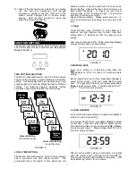
(2) Line up the holes on the mounting bracket with the
holes on your junction box. Using fitting screws
(depending on size of the holes in your junction
box), and attach the mounting bracket to your
junction box (FIGURE 36).
FIGURE 36
(3) Place the gasket in position before wiring.
(4) Connect the brown wire from the fixture to the
brown (Live) power supply wire from your power
source using the wire nuts provided. Connect the
blue wire from the fixture to the blue (Neutral)
power supply wire using the wire nuts provided.
Connect the yellow/green wire from the fixture to
the yellow/green (Earth) power supply wire using
the wire nuts provided (FIGURE 37).
FIGURE 37
(5) Place the wiring box and secure it with the two
screws provided. (FIGURE 38)
FIGURE 38
Note:
THIS EQUIPMENT MUST NOT BE MOUNTED
ON AN OUTLET BOX WHICH IS SUPPORTED BY A
BAR HANGER or equivalent (NE PAS MONTER CET
ÉQUIPEMENT SUR UNE BOÎTE DE SORTIE FIXÉE À
UNE BARRE DE SUSPENSION or equivalent).
Japanese Version
According to the place where you plan to install, choose
whichever suits you most.
>
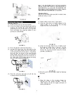
(1) Switch off the power source or wall switch.
(2) Undo the screw which is situated adjacent to the
setting buttons so as to detach the mounting
bracket from the unit. (FIGURE 39)
FIGURE 39
(3) Using the mounting bracket as a template, mark
the positions of fixing hole on the wall. Drill the
hole and insert the plastic wall plug supplied.
Secure the mounting bracket using two screws
provided. (FIGURE 40)
FIGURE 40
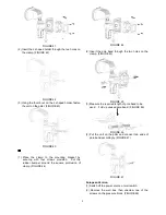
(4) Place the unit to the mounting bracket by fastening
the screw.
?
(1) Place the clamp to the mounting bracket by
securing with four screws provided. Put the
rubber bumper around the square protrusion of
clamp. (FIGURE 41)


