Chapter 1
Introduction
1-7
1.5
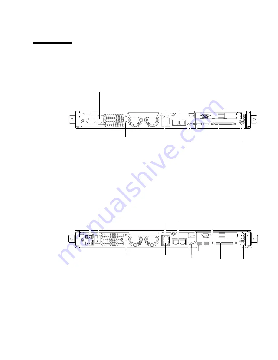
Back Panel
FIGURE 1-4
shows the components on the Sun Fire V120 server’s back panel.
FIGURE 1-4
The Back Panel of the Sun Fire V120 Server
FIGURE 1-5
shows the components on the Netra 120 server’s back panel. Except for
the power inlets, they are identical to the components on the back panel of the Sun
Fire V120.
FIGURE 1-5
The Back Panel of the Netra 120 Server
Power (On/Standby) switch
Optional PCI card
USB ports
SCSI port
Link 0
Link 1
Fault
Power
Grounding studs
Serial B port
Serial A/LOM port
Ethernet ports
Power (On/Standby) switch
Optional PCI card
USB ports
Link 0
Link 1
Fault
Power
Grounding studs
Serial B port
Serial A/LOM port
Ethernet ports
SCSI Port
DC power inlet
AC power inlet
Summary of Contents for Netra 120
Page 10: ...x Sun Fire V120 and Netra 120 Server User s Guide December 2001...
Page 14: ...xiv Sun Fire V120 and Netra 120 Server User s Guide December 2001...
Page 16: ...xvi Sun Fire V120 and Netra 120 Server User s Guide December 2001...
Page 22: ...xxii Sun Fire V120 and Netra 120 Server User s Guide December 2001...
Page 23: ...PART I Installation and Configuration...
Page 24: ......
Page 48: ...3 10 Sun Fire V120 and Netra 120 Server User s Guide December 2001...
Page 64: ...4 16 Sun Fire V120 and Netra 120 Server User s Guide December 2001...
Page 99: ...PART II Remote and Local Management...
Page 100: ......
Page 124: ...8 24 Sun Fire V120 and Netra 120 Server User s Guide December 2001...
Page 138: ...9 14 Sun Fire V120 and Netra 120 Server User s Guide December 2001...
Page 139: ...PART III Troubleshooting and Maintenance...
Page 140: ......
Page 154: ...10 14 Sun Fire V120 and Netra 120 Server User s Guide December 2001...
Page 177: ...PART IV Appendixes...
Page 178: ......
Page 184: ...A 6 Sun Fire V120 and Netra 120 Server User s Guide December 2001...
Page 192: ...C 6 Sun Fire V120 and Netra 120 Server User s Guide December 2001...


