Sun Microsystems DGA 5000 Operator'S Manual Download Page 57


After the test data for Limit Set 2 has been stored the 

“Toggle Limit 

Sets” button will show that Limit Set 1 has been automatically 
reselected and the indicator bands will change accordingly. A figure 
“2” will appear in the toolbar, confirming that data is stored in data 
buffer 2. 

The data stored in the data buffers can be reviewed, printed or deleted 
via the 

The Print Preview Window 

(see 

8.7

). 


8.6  Storing Data in the Data Buffers


Current test readings to which a Limit Set has been applied may be 
temporarily stored in one of the two data buffers. This temporary storage 
allows the second Limit Set to be applied without the loss of the initial 
test results. Data to which Limit Set 1 is applied will be stored in buffer 1 
and data to which Limit Set 2 is applied will be stored in buffer 2. 


Note:


The following description assumes that the Free Measurement


Procedure is performed as outlined in 

8.5: „Free Measurement Test


Procedure‟ 

(i.e. the data to which Limit Set 1 has been applied is to be 

stored before Limit Set 2 is applied). Although this will be the usual 
procedure, it should be noted that it is possible to apply Limit Set 2 
before Limit Set 1 or to apply either Limit Set independently.


To store data in data buffer 1: 

• 

Apply Limit Set 1 using the 

“Toggle Limit Set” button . 
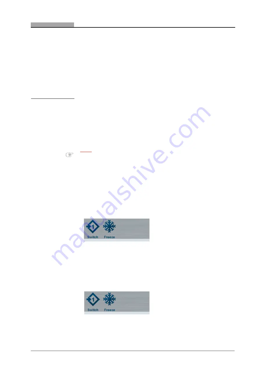


Figure 8-7 

Apply Limit Set 1 


• 

Take the Limit Set 1 gas measurements as outlined i

8.5: „Free 

Measurement Test 

Procedure‟

. 

• 

Press the “Freeze” toolbar button. 


Figure 8-8 

Freeze Limit Set 1 Readings 


48


S

TORING 

D

ATA IN THE 

D

ATA  

B

UFFERS


Summary of Contents for DGA 5000

Page 1: ...EMISSIONS DIAGNOSTIC PLATFORM Operator s Manual HIGH TECH SECURES YOUR FUTURE...

Page 2: ......

Page 3: ...l EMISSIONS DIAGNOSTIC PLATFORM Software Version V 5 X X X Models DGA5000 Geogas5000 Diagnostic Gas Analyser Copyright 2002 2016 Snap on UK Holdings Ltd All rights reserved Part number ZEEEAGB132A 30...

Page 4: ...n contained in this manual is correct complete and up to date the right to change any part of this document at any time without prior notice is reserved Before installing maintaining or operating this...

Page 5: ......

Page 6: ...eral 5 2 2 Gas Bench 5 2 2 1 SGM II 5 3 Introduction 7 3 1 The DGA 5000 8 3 2 Maintenance 8 3 3 Options 8 4 Functional Description 9 4 1 Platform Layout 9 4 2 Gas Module Layout 9 4 2 1 Gas Module Layo...

Page 7: ...ration 29 6 3 Daily Leak Check 30 6 4 HC Residue Check 31 6 5 Settings 32 6 5 1 Fuel Type Selection 32 6 5 2 Speed Factor Setting 32 6 5 3 Lambda AFR Selection 32 6 6 Vehicle Connections 33 6 6 1 RPM...

Page 8: ...9 4 Gas Calibration Check 58 9 5 Check and or Install the O2 Cell 59 9 6 Routine Maintenance Procedures 63 9 6 1 Periodic Checks 63 9 6 2 Filters 63 9 6 3 Sample Probe and Hose 64 9 6 4 Test Leads 65...

Page 9: ...vi...

Page 10: ...04A The Safety Precautions book should be fully understood by every operator We suggest that a copy of of the Safety Precautions bookbe stored near the unit in sight of the operator The Operator s Man...

Page 11: ...k and throughout this manual are reminders to the operator to exercise extreme care when using this unit There are many variations in procedures techniques tools and parts for servicing vehicles as we...

Page 12: ...essages and instructions in the Safety Precautions book this manual and on the unit 1 3 Conventions This manual contains text styles that ask you to pay extra attention Note Suggestion or explanation...

Page 13: ...4 C H A P T E R 1...

Page 14: ...0 0 01 vol vol CO2 0 00 20 00 0 1 vol ppmvol HC 0 9999 1 ppm vol vol O2 0 25 00 0 01 vol O2 4 0 1 vol rpm 0 9999 1 0 C 0 120 F 14 302 Note accuracyaccordingtoOIMLClass0 2 2 1 1 Propane Equivalence Fac...

Page 15: ...6 C H A P T E R 2...

Page 16: ...for performing theemissions tests specified by separate national or international jurisdictions Although this jurisdiction specific software may alter the DGA 5000 standard software described herein t...

Page 17: ...n this manual together with a list of operator service messages and a list of maintenance parts All maintenance operations other than those specifically described in this manual must be carried out by...

Page 18: ...ule Layout SGMII Figure 4 2 The Gas Module Side Bottom Panels 1 USB connection for PC interface 2 Power LED indicator 3 12vDC power input jack 4 O2 Sensor p n7096E4060 31 5 Clean air inlet with charco...

Page 19: ...e assembly 8 Gas sample outlet outlet for gas sample from gas bench 9 Water outlet connect a tube to this outlet to drain water fromthe water removal system 10 Gas sample outlet outlet for gas sample...

Page 20: ...ns For details of the use of drop down menus refer to the Manual 4 4 Drop down Menus For details of Diagnostic Platform System Screens refer to the Manual 5 Diagnostic Platform System Screens For deta...

Page 21: ...imit set 2 see 8 2 Free Measurement Vehicle Setup and 8 5 Free Measurement Test Procedure Toggle Limits 2 Indicates that limit set 2 is currently applied click to toggle to limit set 1 see 8 2 Free Me...

Page 22: ...Settings Selects the Gas Analyser System Settings Gas Analyser System Information Selects Gas Analyser System Information Gas analyser Software Update Allows updated software to be loaded Currently d...

Page 23: ...enu Icons Icon Name Description Gas Calibration Check Initiates the Gas Calibration Check maintenance procedure Check install O2 Cell Initiates the Check and or Install the O2 Cell maintenance procedu...

Page 24: ...15 C H A P T E R 4...

Page 25: ...ance Menu 5 3 Gas Analyser Maintenance Menu The Gas Analyser System Settings Screen 5 4 Gas Analyser System Settings The Gas Analyser System Information Window 5 5 Gas Analyser System Information Deta...

Page 26: ...alyser Menu The following options may be selected Free Measurement Procedure see 5 2 for selection sequence The Petrol Maintenance Menu see 5 3 for selection sequence Note The Free Measurement procedu...

Page 27: ...the toolbar Once the Gas Analyser is switched on it should remain on for the whole working day however it is recommended that the unit should be put into Standby Mode when tests are not being perform...

Page 28: ...nsor checks Diagnostics Calibration procedures Service Technician level only Refer to 5 3 for a description of the Maintenance features and to Chapter Maintenance for details of the available maintena...

Page 29: ...Leak Check Vacuum see 10 2 item 1 Leak Check Gas see 10 3 item 2 Gas Calibration Check see 10 4 item 3 Check and or Install the O2 Cell see 10 5 item 4 Diagnostics Gas Calibration item 5 6 are restric...

Page 30: ...u see 5 2 The Gas Analyser System Settings Screen comprises drop downmenus for the selection of Lambda AFR Summertime On Off LPG composition Use the Summertime On Off drop down menu to switch between...

Page 31: ...ne ratio to 50 50 If the composition is known e g LPG used in the United Kingdom has a composition of 0 Butane 100 Propane this ratio should be selected Note The section marked with the RED outline is...

Page 32: ...g Values displays the composition of the gases used for gas calibration Gas Settings includes approval type gas calibration interval summertime on off setting daily leak check requirement etc Service...

Page 33: ...ext button in the The Print Preview Window Free Measurement procedure only see 8 5 The Notes dialog box will be displayed The vehicle identification information headings entered via the Printout Foote...

Page 34: ...r AFR depending on the setting made in the Gas Analyser System Settings Screen see 5 4 Note Althoughtheprintoutformatallowsalltestparameterstobeshown numerical values will only be shown for the limit...

Page 35: ...panel of the Gas Module see 4 2 Gas Module Layout 6 1 2 Data Connections Communication between the PC Gas Module takes place via the USB Universal Serial Bus connectors located on the Gas Module rear...

Page 36: ...on and that the unit be turned on and off with the Diagnostic Platform main power switch Select the SUN Diagnostic Platform program using either the Windows start menu or the shortcut on the desk top...

Page 37: ...p screen can reappear if a leak check is selected but will not reappear when moving to a different menu or set up screen If the system is configured to require a Daily Leak Check see 6 3 the operator...

Page 38: ...n period Until a successful leak check has been performed all measurements will be blocked and it will not be possible to proceed beyond the Gas Analyser Menu see 6 3 Daily Leak Check below for furthe...

Page 39: ...k check should be carried out prior to the commencement of each day s operation The unit will not be capable of normal operation unless a successful leak check has been carried out within the precedin...

Page 40: ...eck A concentration of more than 0 5 vol co2 detected during the check indicates that vehicle exhaust gases are being drawn into the unit The program will prompt the operator to remove the sample prob...

Page 41: ...Speed Factor selection To set the Speed factor Open the vehicle setup screen Select and apply the Speed Factor as described in 8 Operation The Free Measurement Procedure 6 5 3 Lambda AFR Selection Th...

Page 42: ...Up Refer to the Emissions Diagnostic Platform Operator s Manual 6 2 RPM Measurement and Speed Factor Selection for details of rpm pick up connection 6 6 2 Oil Temperature Probe Refer to the Emissions...

Page 43: ...operating temperature This allows time for the exhaust system to vaporize any residual moisture Never move the analyser by pulling on the probe sample hose or power cord Never drive over the probe sa...

Page 44: ...er oil temperature depends on the engine operating conditions but may be considered acceptable if falling within the range mentioned above During testing engine exhaust gas samples are continuously ga...

Page 45: ...ynamometer Always be sure to unblock the tail pipe when testing is complete Do not leave the sample probe in the tail pipe when measurements are not being made as this will shorten the life of the fil...

Page 46: ...37 C H A P T E R 7...

Page 47: ...rrect drivability problems The drivability and emissions symptoms or combinations of symptoms that can be addressed include Engine will not crank Engine will crank but will not start Engine is hard to...

Page 48: ...isfire Adjustment Lean drop Adjustment Accelerator Pump Power Valve High Fuel Level in Float Chamber Testing the Cooling System for Combustion Gases Fuel Leak Exhaust Leak Testing for Fumes in the Pas...

Page 49: ...ure and engine speed are shown in the nine fields comprising the bulk of the screen The field background will be Green so long as the measured value for a particular parameter falls within the applied...

Page 50: ...e 8 6 Storing Data in the DataBuffers To unfreeze the frozen readings press the Unfreeze button The unfreeze button is only available after the Freeze button has been pressed see 8 6 Storing Data in t...

Page 51: ...Select the number of cylinders in the engine Start the engine and allow to run at idle speed Connect the measurement device Wait for the engine speed to be displayed correctly Press OK to proceed to...

Page 52: ...selected ensure that the correct Butane Propane ratio is entered in Gas Analyser System Settings Screen see 5 4 Failure to set the correct ratio may result in inaccurate lambda calculation Select the...

Page 53: ...icle Setups The vehicle setup currently displayed in the Vehicle Setup Screencan be saved in the PC memory for future use The information stored will be Fuel type Speed Factor Limits On Off Limit set...

Page 54: ...d with the mouse or enter the file name in the file name box Click Open in the dialog box or press the Enter key The loaded set up will be applied in the Free Measurement Screen To load the SUN defaul...

Page 55: ...e Tab key The selected field will be highlighted in Blue Use the Backspace key to delete the current value Enter the required new value Repeat the procedure for all values that are to be altered If re...

Page 56: ...robe fully into the vehicle tail pipe Refer to the notes to 7 2 Measurement Procedure if the test vehicle is equipped with twin tail pipes Select Limit Set 1 see 8 1 The Free Measurement Screen Accele...

Page 57: ...sults Data to which Limit Set 1 is applied will be stored in buffer 1 and data to which Limit Set 2 is applied will be stored in buffer 2 Note The following description assumes that the Free Measureme...

Page 58: ...will appear in the toolbar indicating that the data is stored in data buffer 1 Limit Set 2 will be applied automatically and the Toggle Limit Sets button will changeaccordingly Note If the Undo butto...

Page 59: ...ting that data is now stored in both buffers Limit Set 1 will be automatically applied for the next set of measurements and will be shown by the Toggle Limit Sets button The Freeze button will be auto...

Page 60: ...Set 1 The gas measurements stored in buffer 1 will be deleted To delete data stored in buffer 2 Limit Set 2 press Delete Set 2 The gas measurements stored in buffer 2 will be deleted Note Pressingthed...

Page 61: ...est results is a mandatory requirement of many country specific test procedures see 6 3 Daily Leak Check If the DGA 5000 is configured for an approval type that requires such a daily leak check the ap...

Page 62: ...stabilisation period during which the pump will build up a vacuum in the gas analyser pneumatic circuit The current vacuum will be displayed in mBar and a status bar will indicate a 20 second countdow...

Page 63: ...indicate either a successful or unsuccessful test result Figure 9 3 Leak Check Vacuum Result If the leak check is successful unblock the probe tip store the Probe Sealing Tool in a safe place until it...

Page 64: ...ks occurring in the gas module water circuit Since leaks in the water circuit do not compromise measurement accuracy a successful Leak Check Gas is consideredto fulfill the requirement for a daily lea...

Page 65: ...sly measured and displayed When the proper CO2 threshold has been reached 5 vol the screen will indicate that a 20 second stabilisation period has begun A status bar representing a 20 second countdown...

Page 66: ...e pump will re start and the unit will enter the measurement phase in which the decay in the concentration of CO2 will be determined The vacuum CO2 level and CO2 decay will be continuously measured an...

Page 67: ...ut by the operator as and when necessary using a 1 accuracy gas mixture of 1 3 1 7 vol CO 10 5 11 55 vol CO2 540 660 ppm vol HC Note The Gas Calibration Check should not be confused with the full gas...

Page 68: ...position of the calibration gas The indicated ppm vol reading for HC must be the same as the known concentration of HC in the gas bottle When the check is completed turn off the gas and disconnect the...

Page 69: ...built into the software To check the status of the cell Select the O2 Check Install option from the Gas Analyser Maintenance Menu The O2 Check Install screen will be displayed showing the message CHE...

Page 70: ...s Continue in order to proceed with the installation of a new cell To install a new cell Remove the O2 NO cell cover plate on the rear panel of the gas module if applicable Remove the connector from t...

Page 71: ...howing the auto calibration countdown At the end of the auto calibration the screen will show the message Installation complete and prompt the operator to press Exit to leave the installation procedur...

Page 72: ...uum and 9 3 Leak Check Gas for further information A Gas Calibration Check should be carried out as and when required or when indicated by the system Refer to section 9 4 Gas Calibration Check for fur...

Page 73: ...or abrasions that may cause leaks Follow the leak check procedures in this manual and replace any damaged hoses Use the following test repair procedure if the analyser fails a LeakCheck Vacuum or a L...

Page 74: ...s repaired d If the test fails contact your SUN Service Representative for repair service 9 6 4 Test Leads Inspect all test leads weekly for any cuts kinks or abrasions and replace any faulty pick ups...

Page 75: ...illage from entering the ventilation vents Test leads and the main power cable may be cleaned by using a water free hand cleanser and wiping dry with a cloth 9 7 Error Warning and System Status Messag...

Page 76: ...f the time remaining in that status The windows can either be closed manually to allow access to the screen buttons or will close automatically when the system moves into another status In the event o...

Page 77: ...will appear on the right hand side of the toolbar whenever an error or warning condition is detected Examples of such conditions are messages concerning the status of the O2 Sensor insufficient gas fl...

Page 78: ...in progress 6 Zero required 7 Zero in progress 8 Vacuum O O R 9 Rpm O O R 10 Oil temp O O R 11 NOx O O R 12 O2 O O R 13 CO2 O O R 14 CO O O R 15 HC O O R 16 Channel error 17 HCpropane 18 CO3digits 19...

Page 79: ...r 10 Temperature Error 11 Co2 too high while HC residue check active 12 Gasbench driver error 13 No NO CELL 14 No O2 CELL 15 No Flow 16 No Acceptable new cell 17 Change NO CELL 18 NO CELL gas required...

Page 80: ...t No Description 7096E9321 25 Exhaust Probe Assembly 7009E9317 46 Exhaust Probe Sealing Tool 7096E9061 02 Water Filter 7096E9061 54 Charcoal Filter 7096E4060 31 Oxygen Sensor 1 32981A Water Bowl Coale...

Page 81: ...C H A P T E R 10 MAINTENANCE 72...

Page 82: ...Information Filters see Maintenance Free Measurement Applying Limit Sets 50 Free Measurement Screen 39 Test Procedure 47 Free Measurement Vehicle Setup 42 Editing Limit Sets 46 Fuel Type Selection 43...

Page 83: ...nance P Pop up Window 6 6 Power 27 Print 24 Sample Printout 25 Vehicle Identification 24 Print Preview 50 Propane Equivalence Factor P E F 5 S Safety Precautions 1 Sample Hose Probe see Maintenance Sc...

Page 84: ......

Reviews: