Sun Microsystems 5500 Reference Manual Download Page 41

Chapter 3

CPU/ Boards and Components

3-3

3.2

Filler Panels and Load Boards

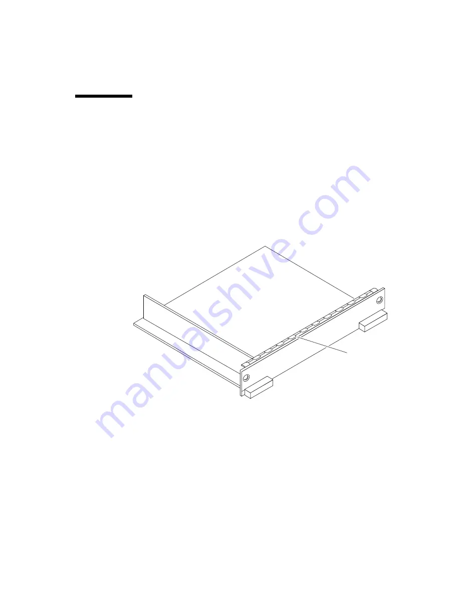
All empty board slots in Enterprise systems must have either a filler panel or a load
board installed. (A load board is distinguished by the presence of centerplane
connectors. A filler panel has no centerplane connectors.)

Empty slots in Enterprise 5500 and 4500 systems must have a filler panel installed
(

FIGURE 3-1

).

Empty slots in Enterprise 6500 systems must have a load board installed
(

FIGURE 3-2

).

Load boards and filler panels are inserted into a board slot with the springfingers
facing down if inserted in the front of the system; the springfingers face up if
inserted in the rear of the system.

FIGURE 3-1

Filler Panel (Enterprise 5500/4500 Only)

Springfingers

Summary of Contents for 5500

Page 1: ...d Palo Alto CA 94303 4900 USA 650 960 1300 Fax 650 969 9131 A Sun Microsystems Inc Business Sun Enterprise 6500 5500 4500 Systems Reference Manual Part No 805 2632 10 RevisionA April 1998 Sun Microsystems Computer Company ...

Page 2: ...998 Sun Microsystems Inc 901 San Antonio Road Palo Alto California 94303 4900 Etats Unis Tous droits réservés Ce produit ou document est protégé par un copyright et distribué avec des licences qui en restreignent l utilisation la copie la distribution et la décompilation Aucune partie de ce produit ou document ne peut être reproduite sous aucune forme par quelque moyen que ce soit sans l autorisat...

Page 3: ... of Terms 1 6 1 5 Internal Options 1 7 2 Safety Precautions and Tools Requirements 2 1 2 1 Safety Precautions 2 1 2 2 Symbols 2 2 2 3 System Precautions 2 3 2 4 Tools Required 2 4 3 CPU Memory Boards and Components 3 1 3 1 Handling Boards and Assemblies 3 2 3 2 Filler Panels and Load Boards 3 3 3 3 Hot Plug Feature 3 4 3 4 CPU Memory Boards 3 5 3 4 1 Removing a Board 3 5 ...

Page 4: ... 4 4 4 4 Hot Plug Feature 4 5 4 5 I O Boards 4 6 4 5 1 GBIC 4 6 4 5 2 Removing a Board 4 8 4 5 3 Installing a Board 4 11 4 5 4 SBus Cards 4 16 4 5 5 Graphics UPA Cards 4 23 4 5 6 GBICs 4 26 4 5 7 PCI Cards 4 29 5 Disk Boards and Components 5 1 5 1 Handling Boards and Assemblies 5 2 5 2 Filler Panels and Load Boards 5 3 5 3 SCSI Termination 5 4 5 4 Hot Plug Feature 5 5 5 5 Disk Boards 5 6 5 5 1 Rem...

Page 5: ...er Supply 7 4 7 4 Power Cooling Module PCM 7 8 7 4 1 Requirements for Redundant Power 7 8 7 4 2 Cooling Requirements 7 9 7 4 3 Troubleshooting a PCM 7 10 7 4 4 Replacing a PCM 7 10 8 Internal SCSI and Storage Devices 8 1 8 1 Device Locations 8 1 8 2 Tape and CD ROM Drives 8 4 8 2 1 Use and Maintenance 8 4 8 2 2 Enterprise 6500 5500 Tape or CD ROM Drive 8 5 8 2 3 Enterprise 4500 Tape or CD ROM Driv...

Page 6: ...d OpenBoot 9 9 9 3 5 Solstice SyMON 9 10 9 4 Specific Problems and Solutions 9 11 9 4 1 Failure of Network Communications 9 11 9 4 2 Resetting and Power Cycling the System from a Remote Console 9 13 10 Flow Diagrams for Troubleshooting 10 1 10 1 No AC or DC Power 10 2 10 2 System Cannot Boot 10 3 10 3 Defective CPU Memory Board 10 4 10 4 Defective I O Interface Board 10 5 10 5 Defective Disk Board...

Page 7: ... 1 Outer Cover Reference Guide 12 2 12 3 2 CD ROM Tape Device Door 12 3 12 3 3 Top Front Bezel 12 4 12 3 4 Front Door 12 5 12 3 5 Rear Door and Kick Panel 12 6 12 3 6 Side Panels 12 7 12 3 7 Fan Tray and Screen 12 8 12 3 8 Stabilizer Bar 12 9 12 4 Internal Access Enterprise 4500 System 12 10 12 4 1 Top Bezel 12 10 12 4 2 Media Tray 12 11 12 5 Powering On the System 12 11 A Specifications A 1 A 1 P...

Page 8: ...B 5 2 System Master Board B 9 B 5 3 SIMMs B 9 B 6 I O Boards B 11 B 6 1 SBus I O Board B 12 B 6 2 Graphics I O Board B 13 B 6 3 PCI I O Board B 14 B 7 Network Interfaces B 15 B 8 Disk Board B 15 B 9 Power Supplies B 16 B 9 1 Power Cooling Modules PCMs B 16 B 9 2 Peripheral Power Supply B 17 B 10 Clock Board B 18 B 11 Disk Trays B 19 B 12 CD ROM Tape Tray B 19 C SCSI Devices C 1 C 1 Media Tray Targ...

Page 9: ... 6 Disk Drives D 5 D 7 CD ROM Tape Drive Media Tray D 5 D 8 Connecting Cables D 6 D 8 1 SCSI D 6 D 8 2 Ethernet D 6 D 8 3 Video Interface D 6 E Non Chassis Field Replaceable Units FRUs E 1 E 1 FRU List E 1 E 2 Enterprise 6500 5500 Systems E 2 E 2 1 System Cabinet Fan Tray Assembly E 2 E 2 2 AC Power Cable E 3 E 2 3 Universal System Cabinet Power Sequencer E 5 E 2 4 Media Tray E 6 E 2 5 Key Switch ...

Page 10: ... F 4 Enterprise 4500 System F 20 G Connectors G 1 G 1 CPU Memory Board G 2 G 1 1 Centerplane Connector G 2 G 1 2 CPU Module Connectors G 4 G 2 I O Boards G 5 G 2 1 Centerplane Connector G 6 G 2 2 SBus Connectors G 7 G 2 3 UPA Connector Location G 8 G 2 4 Ethernet Connector TPE G 9 G 2 5 MII Connector G 9 G 2 6 GBIC Connectors G 10 G 2 7 SCSI Connector G 11 G 2 8 PCI Connectors G 11 G 3 Disk Board ...

Page 11: ...Contents xi G 4 2 Serial Port Connectors G 16 G 4 3 Keyboard and Mouse Connector G 17 H Compliance Statements H 1 Index Index 1 ...

Page 12: ...xii Sun Enterprise 6500 5500 4500 Systems Reference Manual April 1998 ...

Page 13: ...FIGURE 3 1 Filler Panel Enterprise 5500 4500 Only 3 3 FIGURE 3 2 Load Board Enterprise 6500 Systems Only 3 4 FIGURE 3 3 Unlocking and Locking Quarter Turn Access Slots 3 6 FIGURE 3 4 CPU Memory Board 3 6 FIGURE 3 5 Enterprise 6500 Board Locations 3 8 FIGURE 3 6 Enterprise 5500 4500 Board Locations 3 9 FIGURE 3 7 Board Replacement 3 10 FIGURE 3 8 UltraSPARC II Module Connectors 3 12 FIGURE 3 9 Ultr...

Page 14: ...rd Locations 4 12 FIGURE 4 10 Enterprise 5500 4500 Board Locations 4 13 FIGURE 4 11 Board Replacement 4 14 FIGURE 4 12 SBus I O Board SBus Card Connectors 4 16 FIGURE 4 13 Graphics I O Board SBus Card Connectors 4 16 FIGURE 4 14 Locking and Unlocking Standoffs 4 17 FIGURE 4 15 Removing or Installing an SBus Card 4 18 FIGURE 4 16 SBus Card Rear Panel with Adapter 4 19 FIGURE 4 17 Card Retainer 4 19...

Page 15: ...GURE 6 1 Clock Board Block Diagram 6 3 FIGURE 6 2 Clock Board 6 5 FIGURE 7 1 Peripheral Power Supply 7 3 FIGURE 7 2 Quarter Turn Access Slot 7 4 FIGURE 7 3 Replacing the Enterprise 6500 5500 PPS 7 5 FIGURE 7 4 Replacing the Enterprise 4500 PPS 7 6 FIGURE 7 5 PCM 7 8 FIGURE 7 6 PCM Front and Rear Installation 7 11 FIGURE 7 7 Quarter Turn Access Slots 7 11 FIGURE 8 1 Enterprise 6500 System Storage D...

Page 16: ...ise 6500 and 5500 11 2 FIGURE 11 2 AC Power Switch Enterprise 6500 and 5500 11 3 FIGURE 11 3 Key switch Enterprise 4500 11 4 FIGURE 11 4 AC Power Switch Enterprise 4500 11 4 FIGURE 11 5 Rear Screen and Kick Panel 11 5 FIGURE 11 6 CPU Reset Switch on Clock Board 11 7 FIGURE 11 7 System Status LEDs on the Enterprise 6500 5500 Front Panel 11 8 FIGURE 11 8 Status LEDs on the Enterprise 4500 Front Pane...

Page 17: ...ving the Front Bezel E 8 FIGURE E 6 Removing the Cable Assemblies From the Front of the SCSI Adapter Tray E 9 FIGURE E 7 Removing the Two Screws that Attach the media tray to the Flange E 11 FIGURE E 8 Removing the Two Screws that Attach the media tray to the Cabinet Pillar E 12 FIGURE E 9 Removing the Screw from the Left Pillar E 13 FIGURE E 10 Removing the Two Screws from the Right Pillar E 14 F...

Page 18: ...ard Assembly F 14 FIGURE F 13 Graphics I O Board Assembly F 15 FIGURE F 14 PCI I O Board Assembly F 16 FIGURE F 15 Clock Board Assembly F 17 FIGURE F 16 Disk Board Assembly F 18 FIGURE F 17 Load Board Assembly F 19 FIGURE F 18 Enterprise 4500 System Front View F 20 FIGURE F 19 Enterprise 4500 System Rear View F 21 FIGURE F 20 Key Switch Tray F 21 FIGURE F 21 Fan Tray Assembly F 22 FIGURE F 22 Cent...

Page 19: ...6 I O Board MII Connector Locations G 9 FIGURE G 17 I O Board GBIC 0 Connector Locations G 10 FIGURE G 18 I O Board GBIC 1 Connector Locations G 10 FIGURE G 19 I O Board SCSI Connector Locations G 11 FIGURE G 20 PCI 0 and 1 Connectors G 11 FIGURE G 21 Disk Board Connector Locations G 12 FIGURE G 22 Disk Board Centerplane Connector Location G 12 FIGURE G 23 Disk Board SCSI In Connector Location Upp...

Page 20: ...xx Sun Enterprise 6500 5500 4500 Systems Reference Manual April 1998 ...

Page 21: ...Status LED Codes 9 5 TABLE 9 3 Modular Power Supply LED Codes 9 7 TABLE 9 4 Remote Console Commands 9 13 TABLE 11 1 LED Status Indicators 11 9 TABLE 12 1 Cover Removal by Assembly 12 2 TABLE A 1 Enterprise 6500 5500 Physical Specifications A 1 TABLE A 2 Enterprise 6500 5500 Clearance and Service Access A 1 TABLE A 3 Enterprise 6500 5500 Shipping Specifications A 2 TABLE A 4 Enterprise 4500 Physica...

Page 22: ...nd Altitude Limits A 4 TABLE A 10 Enterprise 4500 Temperature Humidity and Altitude Limits A 4 TABLE C 1 Media Tray Default SCSI ID Numbers C 1 TABLE C 2 Disk Board Default SCSI Disk Drive ID Numbers C 2 TABLE C 3 Internal SCSI Lengths Approximate C 3 TABLE D 1 Example of CPU Placement D 4 TABLE E 1 List of Field Replaceable Units E 1 TABLE F 1 List of Replaceable Components F 2 ...

Page 23: ...ation on basic UNIX commands and procedures such as shutting down the system booting the system and configuring devices See one or more of the following for this information Solaris 2 x Handbook for SMCC Peripherals which contains Solaris 2 x software commands AnswerBook online documentation for the Solaris 2 x software environment Other software documentation that you received with your system ...

Page 24: ...iles You have mail AaBbCc123 What you type when contrasted with on screen computer output su Password AaBbCc123 Book titles new words or terms words to be emphasized Command line variable replace with a real name or value Read Chapter 6 in the User s Guide These are called class options You must be root to do this To delete a file type rm filename TABLE P 2 Shell Prompts Shell Prompt C shell machi...

Page 25: ...ise 6x00 5x00 4x00 3x00 Systems 805 3530 Options Sun Enterprise Expansion Cabinet Installation and Service Manual 805 4009 Sun Enterprise 6 5 4 3x00 Systems Board Installation Guide 805 4007 4 Mbyte UltraSPARC II Installation Guide 805 1150 Sun Enterprise 6 5 4 3x00 Systems SIMM Installation Guide 802 5032 SBus and Graphics I O Boards 100 MB sec Fibre Channels for Sun Enterprise 6 5 4 3x00 Systems...

Page 26: ...ling by unqualified personnel can cause serious damage to this equipment Unqualified personnel who tamper with this equipment may be held liable for any resultant damage to the equipment Individuals who remove any outer panels or open covers to access this equipment must observe all safety precautions and ensure compliance with skill level requirements certification and all applicable local and na...

Page 27: ...enclosures This manual has specific details for two styles used for the Sun Enterprise 6500 5500 and 4500 servers FIGURE 1 1 Many boards and modules are used in all three enclosures including the CPU Memory board various types of I O boards the Disk board processor modules memory modules most power supplies and the CD ROM drive ...

Page 28: ...nterprise 6500 5500 systems is Data center system cabinet system cabinet 16 slot 6500 or 8 slot 5500 card cage Power cooling modules 2 Quad fan tray Clock board CPU Memory board UltraSPARC II module Main memory I O board Peripheral power supply AC power sequencer Media tray for removable SCSI media drives such as the SunCD drive System cabinet Standalone enclosure Enterprise 6500 and 5500 systems ...

Page 29: ...nterprise 5500 system The Enterprise 6500 system is similar but has a larger card cage FIGURE 1 2 Front View of the Enterprise 5500 System Cabinet FIGURE 1 3 shows the rear view of the Enterprise 6500 system The Enterprise 5500 system is similar With panels Without panels ...

Page 30: ...1 4 Sun Enterprise 6500 5500 4500 Systems Reference Manual April 1998 FIGURE 1 3 Rear View of the Enterprise 6500 System Cabinet With rear door Without rear door ...

Page 31: ...ezels for Enterprise 6500 5500 System Two Examples 1 3 Enterprise 4500 System The minimum configuration for the Enterprise 4500 system is 8 slot card cage Power cooling modules 2 Fan box Clock board CPU Memory board UltraSPARC II module Main memory SBus I O board Peripheral power supply AC power sequencer Media tray for removable SCSI media drives such as the SunCD drive Tape library Blank panel ...

Page 32: ...n and boards in the rear of the card cage are installed component side up Similarly the orientation of the power cooling modules installed in the rear of the system chassis is opposite the orientation of power cooling modules in the front of the system chassis Viewer orientation Since boards modules and power cooling modules may be located on either side of the Enterprise server chassis centerplan...

Page 33: ...the rear of the card cage although CPU Memory boards and I O boards will work in either the front or rear of the card cage Disk boards 2 per system must use slot 15 if only 1 is installed 4 per system Can be installed only in slot 14 and slot 15 in the Enterprise 6500 system For easier Disk boards cabling CPU Memory boards can be installed in the front and Disk boards in the rear of the Enterprise...

Page 34: ...erprise 6500 and 5500 system cabinets support Sun StorEdge A5000 disk arrays The expansion cabinet also supports A5000 disk arrays Refer to documentation that comes with the disk arrays and the expansion cabinet StorEdge Flexipack or L400 The Enterprise 6500 and 5500 system cabinets support the StorEdge Flexipack or L400 tape unit The expansion cabinet also supports the StorEdge Flexipack or L400 ...

Page 35: ...cautions TABLE 2 1 Safety Precautions Item Problem Precaution Wrist or foot strap ESD Wear a conductive wrist strap or foot strap when handling printed circuit boards ESD mat ESD An approved ESD mat provides protection from static damage when used with a wrist strap or foot strap The mat also cushions and protects small parts that are attached to printed circuit boards Cover panels System damage a...

Page 36: ...ontact Surface may cause injury if touched ALTERNATING CURRENT OR VOLTAGE ON OFF STAND BY The system is in standby mode and the operating system is halted The circuit breaker can be turned off DIAGNOSTICS System is powered on If system is rebooted POST will display extended diagnostic messages RUNNING on a board or control panel System board is operating normally LOCKED On a board this means the c...

Page 37: ...ibed in Section 1 2 Preparing the Electrical Circuits in the Sun Enterprise 6500 5500 4500 Systems Installation Guide part number 805 2631 Caution DO NOT make mechanical or electrical modifications to the cabinet Sun Microsystems is not responsible for regulatory compliance of modified cabinets COMPONENT POWER The board is receiving DC power SERVICE NEEDED The system has detected a hardware failur...

Page 38: ...ocedures in this book you will need some or all of these tools Screwdriver slotted 3 16 inch Screwdriver Phillips 2 Screwdriver Phillips 1 Hex driver M 4 Hex driver 3 16 inch Hex driver 9 mm Wrench 13 mm supplied with the system DIP IC extraction tool ESD mat Grounding wrist strap Needlenose pliers Hex driver 3 32 Torque screwdriver supplied with the system preset to 6 inch pounds ...

Page 39: ...e 3 4 CPU Memory Boards page 3 5 UltraSPARC II Modules page 3 11 Memory Modules SIMMs page 3 16 Connectors page G 2 For your protection also observe the following safety precautions when setting up your equipment Follow all cautions warnings and instructions marked on the equipment Never push objects of any kind through openings in the equipment as they may touch dangerous voltage points or short ...

Page 40: ...nnectors and components have very thin pins that bend easily Do not use an oscilloscope probe on the components The soldered pins are easily damaged or shorted by the probe point Transport the board in an antistatic bag Be careful of small parts located on the component side of the board Be careful not to drag boards across surfaces as board components are easily damaged Caution The heatsinks on t...

Page 41: ... has no centerplane connectors Empty slots in Enterprise 5500 and 4500 systems must have a filler panel installed FIGURE 3 1 Empty slots in Enterprise 6500 systems must have a load board installed FIGURE 3 2 Load boards and filler panels are inserted into a board slot with the springfingers facing down if inserted in the front of the system the springfingers face up if inserted in the rear of the ...

Page 42: ...tem can be reconfigured so that the board containing the failed components is placed in low power mode and is no longer accessible Caution The peripheral power supply provides the precharge voltages required for hot plug Do not attempt hot plug of a system component if the power supply is missing or inoperative Use prtdiag 1M to determine the status of the peripheral power supply Caution If the me...

Page 43: ...rd 3 4 1 1 Removing a Board from a Powered On System Caution Remove a board from a powered on system only after the ASR software has disabled the board If a board has not been disabled by the ASR software then the operating system should be halted and the system powered off prior to board removal See Chapter 11 Powering Off and On and then see Section 3 4 1 2 Removing a Board From a Powered Off Sy...

Page 44: ...d simultaneously to unseat the board centerplane connector from the centerplane receptacles FIGURE 3 4 FIGURE 3 4 CPU Memory Board 4 If a board is not immediately replaced a load board Enterprise 6500 systems only or a filler panel Enterprise 4500 and 5500 systems only must be installed in its place See Section 3 2 Filler Panels and Load Boards Unlocked Locked Extraction lever ...

Page 45: ...ds 3 4 2 Installing a Board 3 4 2 1 Board Slot Selection Note It is suggested that CPU Memory boards be installed in the front slots and I O and Disk boards be installed in the rear slots because of cabling Should the need arise however any of these three board types can be placed in any board slot with the exception of slot 1 Slot 1 should be used for an I O board because it is the only slot conn...

Page 46: ...3 8 Sun Enterprise 6500 5500 4500 Systems Reference Manual April 1998 FIGURE 3 5 Enterprise 6500 Board Locations Front view Slot 0 2 4 6 8 10 12 14 Slot 1 3 5 7 9 11 13 15 Rear view PCM ...

Page 47: ... and power requirements The PCMs must be installed adjacent to populated board slots to ensure the fan in the PCM can cool the respective boards Note All empty board slots in Enterprise 4500 or 5500 systems must have a filler panel installed to ensure proper cooling and for EMI protection All empty slots in Enterprise 6500 systems must have load boards installed Front view Rear view Slot 0 2 4 6 S...

Page 48: ...ked arrow indicates unlocked position as you slide the board toward the centerplane receptacles FIGURE 3 3 and FIGURE 3 4 The board will not seat fully unless the levers are in this starting position and both quarter turn access slots are unlocked Caution DO NOT FORCE any board into a slot it can cause damage to the board and system The board should insert and seat smoothly If it binds remove the ...

Page 49: ...ng will be displayed on the monitor if the system is powered on Example depicts screen output when a new CPU Memory board has been hot plugged into slot 6 of an operating Enterprise system This screen output indicates that the board has been detected by the system and is in the low power mode Additionally any subsequent prtdiag 1M output would include information for board slot 6 Again note that t...

Page 50: ...rounding wrist strap field kit must be used when handling the modules Always handle the modules by the edges and not by the smaller black heat sinks that break easily if handled improperly Do not handle the modules by touching the gold pins on the compression connectors Natural oils on the hands cause these connectors to oxidize and corrode over a period of time resulting in the need for module cl...

Page 51: ...ector pins to the board mating surfaces FIGURE 3 9 FIGURE 3 9 Ultra SPARC Module Connector Detail 1 Use the procedures in Section 3 4 1 Removing a Board to remove the applicable CPU Memory board Hot Surface The heatsinks on the UltraSPARC II modules may be hot Use caution when removing or installing UltraSPARC II modules and avoid contact 2 Use a 3 32 Hex driver to loosen all screws on each of the...

Page 52: ...e Removal and Replacement 4 Place the module in an antistatic bag 3 4 4 2 Installing a Module To maximize performance when installing UltraSPARC II modules on a CPU Memory board use all CPU 0 connectors on the lowest numbered slot to the highest numbered slot If there are modules remaining use the CPU 1 connectors in the same order Note Screws on the UltraSPARC II modules must be tightened to 6 in...

Page 53: ...board opposite the module s smaller board connector This acts as a standoff for the module as well as an alignment pin 4 Holding the module by the edges align the module over the two board receptacles use the single standoff and the alignment pins on the module compression connector as a guide See FIGURE 3 9 and FIGURE 3 10 5 Rest the module on the board standoff aligning the compression connector...

Page 54: ...cient force can cause an incomplete electrical connection FIGURE 3 11 Tightening Compression Connector Screws 7 Use the procedures in Section 3 4 2 Installing a Board to replace the applicable CPU Memory board 3 4 5 Memory Modules SIMMs The CPU Memory board has 16 SIMM sockets which are divided into two banks of 8 SIMMs each Bank 0 and Bank 1 Bank 0 and Bank 1 SIMMs occupy alternate slot locations...

Page 55: ...from which the SIMM is to be removed See Section 3 4 1 Removing a Board 2 Attach a wrist strap and place an antistatic surface next to the system TABLE 3 1 SIMM vs DRAM SIMM DRAM 8 Mbyte 1 Mbyte x4 32 Mbyte 4 Mbyte x4 128 Mbyte 16 Mbyte x4 B0 J3100 B0 J3200 B0 J3400 B0 J3500 B0 J3300 B0 J3600 B0 J3800 B0 J3700 B1 J3101 B1 J3501 B1 J3301 B1 J3401 B1 J3601 B1 J3701 B1 J3801 B1 J3201 Bank 0 Bank 1 CP...

Page 56: ...sides of the SIMM connector FIGURE 3 13 FIGURE 3 13 Ejecting a SIMM 5 Holding the SIMM by its edges remove it from the slot and place it on an antistatic surface 3 4 5 2 Installing a Memory Module Requirements All banks must have the same size SIMMs however SIMMs from different manufacturers are interchangeable in a single bank if the SIMMs all have the same capacity and speed Sort the SIMMs into ...

Page 57: ...ation 1 Place the CPU Memory board on which the SIMM is to be installed on an antistatic mat 2 Carefully remove the new SIMM from its protective packaging and place it on an antistatic surface The bag that the SIMM is packed in makes a good antistatic surface 3 Press down on the ejector levers at both ends of the SIMM connector slot that will receive the new SIMM The connector slot will not accept...

Page 58: ...3 20 Sun Enterprise 6500 5500 4500 Systems Reference Manual April 1998 FIGURE 3 14 Orienting a SIMM FIGURE 3 15 Installing a SIMM Notch alignment ...

Page 59: ...ards page 4 6 SBus Cards page 4 16 Graphics UPA Cards page 4 23 GBICs page 4 26 PCI Cards page 4 29 Connectors page G 5 For your protection also observe the following safety precautions when setting up your equipment Follow all cautions warnings and instructions marked on the equipment Never push objects of any kind through openings in the equipment as they may touch dangerous voltage points or sh...

Page 60: ...ectors and components have very thin pins that bend easily Do not use an oscilloscope probe on the components The soldered pins are easily damaged or shorted by the probe point Transport the board in an antistatic bag Be careful of small parts located on the component side of the board Be careful not to drag boards across surfaces as board components are easily damaged Caution The heatsinks on the...

Page 61: ...s no centerplane connectors Empty slots in Enterprise 5500 and 4500 systems must have a filler panel installed FIGURE 4 1 Empty slots in Enterprise 6500 systems must have a load board installed FIGURE 4 2 Load boards and filler panels are inserted into a board slot with the springfingers facing down if inserted in the front of the system the springfingers face up if inserted in the rear of the sys...

Page 62: ...ise 6500 System Only 4 3 SCSI Termination The I O board in slot 1 controls the internal media tray devices Therefore the external SCSI connector on the I O board in slot 1 of a system must be terminated with a SCSI terminator FIGURE 4 3 FIGURE 4 3 SCSI Terminator Springfingers Centerplane connectors ...

Page 63: ...provides the precharge voltages required for hot plug Do not attempt hot plug of a system component if the power supply is missing or inoperative Use prtdiag 1M to determine the status of the peripheral power supply Caution If the message NOTICE Hot Plug not supported in this system is displayed during boot do NOT attempt hot plug in this system or damage to the hardware will occur The hot plug fe...

Page 64: ...O board Each board has three LEDs that provide board status codes FIGURE 4 4 through FIGURE 4 6 4 5 1 GBIC Each SBus and Graphics I O board provides mounting for two GBIC interfaces A GBIC Gigabit Interface Converter is a hot pluggable unit that converts any of the standard Fibre Channel connectors and signaling technologies The GBIC Fibre Channel referred to in this manual is 100 Mbytes second FI...

Page 65: ...Chapter 4 I O Boards and Components 4 7 FIGURE 4 5 Graphics I O Board with 100 MB sec Fibre Channel FIGURE 4 6 PCI I O Board GBIC ...

Page 66: ...ard In addition onboard devices on the PCI I O board provide Fast Ethernet 10 100 Mbit and Fast Wide SCSI interfacing 4 5 2 Removing a Board Note It is not necessary to remove an I O board from the card cage to remove and replace GBICs A GBIC may be removed and replaced live without removing power from the system or board However the necessary software precautions must be taken whenever the I O pa...

Page 67: ...side up installed in rear of card cage 2 Unfasten any cable connectors from the front panel and set them aside Label cables to identify them for reconnection later 3 Use a Phillips 1 screwdriver to mechanically release the board from the system card cage Insert the screwdriver into each quarter turn access slot the slots are located on the left and right sides of the board front panel and then tur...

Page 68: ...lips 1 screwdriver to mechanically release the board from the system card cage Insert the screwdriver into each quarter turn access slot the slots are located on the left and right sides of the board front panel and then turn a quarter turn so that the arrow points to the unlocked position FIGURE 4 7 2 Unfasten any cable connectors from the front panel and set them aside Label cables to identify t...

Page 69: ...talled in the rear slots because of cabling Should the need arise however any of these three board types can be placed in any of the numbered board slots with the exception of slot 1 Slot 1 should be used by the first I O board because it is the only slot connected to the onboard SCSI devices The first CPU Memory board is placed in slot 0 followed sequentially by all remaining even numbered slots ...

Page 70: ...4 12 Sun Enterprise 6500 5500 4500 Systems Reference Manual April 1998 FIGURE 4 9 Enterprise 6500 Board Locations Front View Slot 0 2 4 6 8 10 12 14 Slot 1 3 5 7 9 11 13 15 Rear View ...

Page 71: ...ower requirements The PCMs must be installed adjacent to populated board slots to ensure the fan in the PCM can cool the respective boards Note All empty board slots in Enterprise 6500 systems must have a load board installed to ensure proper cooling and for EMI protection All empty board slots in Enterprise 5500 or 4500 systems must have a filler panel installed Slot 0 2 4 6 Slot 1 3 5 7 PCM Fron...

Page 72: ... indicates unlocked position as you slide the board toward the centerplane receptacles The board will not seat fully unless the levers are in this starting position and the access slots are unlocked See FIGURE 4 7 and FIGURE 4 8 on page 4 10 Caution DO NOT FORCE any board into a slot this can cause damage to the board and system The board should insert and seat smoothly If it binds remove the boar...

Page 73: ...nal media tray devices Therefore the external SCSI connector on the I O board in slot 1 of a system must be terminated with a SCSI terminator FIGURE 4 3 6 Terminate the board SCSI connector if required see above note 7 Once the board has been installed a message similar to the following will be displayed on the monitor if the system is powered on The example depicts screen output when a new I O bo...

Page 74: ...nual April 1998 4 5 4 SBus Cards There are three SBus card locations on the SBus I O board the Graphics I O board has two FIGURE 4 12 SBus I O Board SBus Card Connectors FIGURE 4 13 Graphics I O Board SBus Card Connectors SBus 0 SBus 1 SBus 2 SBus 0 SBus 2 ...

Page 75: ...moved 3 Remove the two screws that secure the SBus card to the back panel Save the screws for installation of a replacement SBus card or a filler panel 4 Unlock the SBus card by pulling up the tips of the two standoff FIGURE 4 14 5 Hold the card by the edges near the connector and gently rock the card back and forth to loosen it from the socket You may have to remove the SBus cards or the FFB card...

Page 76: ...anel use the screws that were removed in Step 3 Caution Be sure to install the filler panel right side up Installing it upside down creates a gap at the top edge of the SBus slot opening that can impair system cooling and FCC regulatory compliance 9 Replace the I O board Use the procedures in Section 4 5 3 Installing a Board on page 4 11 4 5 4 3 Installing an SBus Card Removing Adapter and Card Re...

Page 77: ...he adapter bracket and the screws are not needed for this installation FIGURE 4 16 SBus Card Rear Panel with Adapter 3 Remove the black plastic card retainer shipped with the card FIGURE 4 17 Spread the ends of the retainer apart to remove it from the card the retainer is not needed for this installation FIGURE 4 17 Card Retainer Link Integrity Test Note If the new SBus card does not have a link i...

Page 78: ... 1 Place the SBus card on an antistatic mat 2 For DSBE S and FSBE S cards remove the two outer retaining screws FIGURE 4 18 but do NOT remove the middle screw or the springfinger Use a 0 Phillips screwdriver and a 3 16 nut driver or socket wrench 3 For DSBE S and FSBE S cards configure jumper J0302 for Link Integrity Test functionality See FIGURE 4 18 DSBE S or FIGURE 4 19 FSBE S a Put the shunt o...

Page 79: ...Chapter 4 I O Boards and Components 4 21 FIGURE 4 18 DSBE S SBus Card FIGURE 4 19 FSBE S SBus Card Jumper J0302 Springfinger Back panel Phillips screw Jackscrews J0302 ...

Page 80: ...ins in the connector to make sure they are not bent 6 Hold the SBus card at an angle and guide the SBus card face plate under the springfingers and against the rear face of the I O board front panel See FIGURE 4 15 on page 4 18 The I O connectors of the SBus card should be visible through the opening in the back panel 7 Hold the card by the edges nearest the SBus connector and place the card over ...

Page 81: ...that accommodates graphics UPA cards FIGURE 4 21 FIGURE 4 21 Graphics UPA Card Connector Location 4 5 5 1 Removing a Graphics UPA Card 1 Use the procedures in Section 4 5 2 Removing a Board to remove the applicable Graphics I O board 2 Locate the card FIGURE 4 22 3 Remove the two screws that secure the card to the Graphics I O board front panel Save the screws for installation of a replacement car...

Page 82: ...the face plate out from the back panel opening FIGURE 4 22 FIGURE 4 22 Removing or Installing a Graphics UPA Card 7 Place the card in an antistatic bag 8 If the graphics UPA card is not immediately replaced install a filler panel part number 340 2305 on the Graphics I O board back panel opening To secure the filler panel use the screws that were removed in Step 3 Caution Be sure to install the fil...

Page 83: ...card remove the two screws and detach the filler panel Retain the screws to attach the graphics UPA card to the back panel unless the card has a wide connector or set of connectors 6 Unlock the two standoffs for the UPA connector slot FIGURE 4 14 7 Hold the card at an angle and guide the card face plate under the springfingers and against the rear face of the Graphics I O board front panel The I O...

Page 84: ...back panel screws to secure the card to the Graphics I O board front panel FIGURE 4 15 13 Use the procedures in Section 4 5 3 Installing a Board to replace the Graphics I O board 4 5 6 GBICs Each SBus and Graphics I O board has two onboard connectors each connector accommodates one GBIC 100 MB sec Fibre Channel 4 5 6 1 Removing a GBIC 1 Locate the GBIC to be removed FIGURE 4 23 or FIGURE 4 24 FIGU...

Page 85: ...Chapter 4 I O Boards and Components 4 27 FIGURE 4 24 Graphics I O Board GBIC Connector Locations GBIC 1 GBIC 0 ...

Page 86: ...d panel FIGURE 4 25 FIGURE 4 25 Removing or Installing a GBIC 4 5 6 2 Installing a GBIC 1 Locate the GBIC slot for installation FIGURE 4 24 2 Ensure correct orientation for insertion The alignment slots should be on the bottom of the GBIC FIGURE 4 25 3 Insert the GBIC into the I O board panel slot and then push in to firmly seat the card An audible click indicates the GBIC is properly seated to th...

Page 87: ...d with 5 0V or 3 3V connector receptacles only and those that can be used with either voltage type Sun PCI I O boards are shipped with two 5 0V riser cards installed and two 3 3V riser cards not installed If you are switching to a 3 3V PCI card you must replace the existing 5 0V riser card with the 3 3V riser card See Section 4 5 7 3 Replacing Riser Cards on page 4 33 4 5 7 1 Removing a PCI Card 1...

Page 88: ... to be removed with your index fingers on either side of the card where it mates with the connector on the riser card thumbs against the connector b Loosen the card from the PCI bus connector and the catch mechanism by firmly pushing with your thumbs against the PCI bus connector while grasping the card edge with the index fingers of both hands 5 Once the card is free of the PCI bus connector and ...

Page 89: ...Chapter 4 I O Boards and Components 4 31 FIGURE 4 27 PCI Card Removal Catch mechanism ...

Page 90: ...FIGURE 4 28 Note PCI I O boards purchased from Sun Microsystems are shipped with the JTAG Test Jumper disabled or removed on both of the 5 0V riser cards installed on the board FIGURE 4 28 JTAG Test Jumper 3 Align the PCI card so that the PCI bus connector mates with the PCI I O board PCI bus connector making sure that the external connector end of the card is retained on one side by the opening i...

Page 91: ...the edge of the PCI card and then tighten the screw securing the standoff 6 Use the procedures in the Section 4 5 3 Installing a Board on page 4 11 to replace the I O board 4 5 7 3 Replacing Riser Cards 1 Use the procedures in Section 4 5 2 Removing a Board on page 4 8 to remove the applicable I O board 2 If a PCI card is already installed in the slot designated for replacement of the riser card r...

Page 92: ...r on the system and when the banner appears press the Stop A keys to interrupt the boot process and get the ok prompt 2 Use the show devs command to list the system devices You should see entries similar to the entries in the example below for the PCI I O board that you installed ok show devs pci 3 2000 pci 2 pci 3 2000 pci 2 SUNW isptwo 4 identifies adapter SCSI interface pci 3 2000 pci 2 SUNW hm...

Page 93: ...cards if necessary Also verify that the JTAG Test Jumper on the PCI card is disabled or removed See Section 4 5 7 2 Replacing or Installing a PCI Card 4 5 7 5 Flash PROM The Sun Enterprise 6500 5500 4500 system I O boards use flash PROMs Flash PROMs may be reprogrammed and can be updated to the latest firmware code Refer to the Sun Enterprise 6x00 5x00 4x00 3x00 System Flash PROM Programming Guide...

Page 94: ...4 36 Sun Enterprise 6500 5500 4500 Systems Reference Manual April 1998 ...

Page 95: ...ion page 5 4 Hot Plug Feature page 5 5 Disk Boards page 5 6 Disk Drives page 5 12 Connectors page G 12 For your protection also observe the following safety precautions when setting up your equipment Follow all cautions warnings and instructions marked on the equipment Never push objects of any kind through openings in the equipment as they may touch dangerous voltage points or short out component...

Page 96: ...e the board on a hard surface Use a cushioned antistatic mat The board connectors and components have very thin pins that bend easily Do not use an oscilloscope probe on the components The soldered pins are easily damaged or shorted by the probe point Transport the board in an antistatic bag Be careful of small parts located on the component side of the board Be careful not to drag boards across s...

Page 97: ...s no centerplane connectors Empty slots in Enterprise 5500 and 4500 systems must have a filler panel installed FIGURE 5 1 Empty slots in Enterprise 6500 systems must have a load board installed FIGURE 5 2 Load boards and filler panels are inserted into a board slot with the springfingers facing down if inserted in the front of the system the springfingers face up if inserted in the rear of the sys...

Page 98: ...ril 1998 FIGURE 5 2 Load Board Enterprise 6500 Systems Only 5 3 SCSI Termination The last or only Disk board in a system must have the SCSI out connector terminated with a SCSI terminator FIGURE 5 3 FIGURE 5 3 SCSI Terminator Springfingers Centerplane connectors ...

Page 99: ...des the precharge voltages required for hot plug Do not attempt hot plug of a system component if the peripheral power supply is missing or inoperative Use prtdiag 1M to determine the status of the peripheral power supply Caution If the message NOTICE Hot Plug not supported in this system is displayed during boot do NOT attempt hot plug in this system or damage to the hardware will occur The hot p...

Page 100: ... software has disabled the board If a board has not been disabled by the ASR software then the operating system should be halted and the system powered off prior to board removal See Chapter 11 Powering Off and On and then Section 5 5 1 2 Removing a Board from a Powered Off System 1 Ensure that the board has been disabled by the ASR software See Section 5 4 Hot Plug Feature Once disabled by ASR on...

Page 101: ...points to the unlocked position FIGURE 5 4 FIGURE 5 4 Unlocking and Locking Quarter Turn Access Slots 4 Pull the ends of both extraction levers outward simultaneously to unseat the board centerplane connector from the centerplane receptacles FIGURE 5 5 FIGURE 5 5 Disk Board 5 If a board is not immediately replaced a filler panel or a load board for Enterprise 6500 systems only must be installed in...

Page 102: ...d in the front slots and I O and Disk boards be installed in the rear slots because of cabling Should the need arise however any of these three board types can be placed in any of the numbered board slots with these exceptions Slot 1 Slot 1 should be used by the first I O board because it is the only slot connected to the onboard SCSI devices Slots 14 and 15 In Enterprise 6500 systems Disk boards ...

Page 103: ...o cooling and power requirements The PCMs must be installed adjacent to populated board slots to ensure the fan in the PCM can cool the respective boards Note All empty board slots in Enterprise 4500 or 5500 systems must have a filler panel installed to ensure proper cooling All empty slots in Enterprise 6500 systems must have load boards installed Front view Rear view Slot 0 2 4 6 Slot 1 3 5 7 PC...

Page 104: ...locked position as you slide the board toward the centerplane receptacles See FIGURE 5 4 on page 5 7 and FIGURE 5 5 on page 5 7 The board will not seat fully unless the levers are in this starting position and both quarter turn access slots are unlocked Caution DO NOT FORCE any board into a slot this can cause damage to the board and system The board should insert and seat smoothly If it binds rem...

Page 105: ...er you must use a 2 meter cable part number 530 1885 sold separately 6 If the Disk board is the last or only board in the SCSI chain terminate the SCSI out connector on the disk board The Disk board kit includes a fast wide SCSI terminator part number 150 2267 7 Replace or connect all other necessary cables to the fronts of the boards 8 Once the Disk board has been installed a message similar to t...

Page 106: ...the SCSI Host Adapter If all I O boards are installed in the rear use a 2 meter SCSI cable sold separately to connect the Disk board to the SCSI Host Adapter Route the cable down the side of the card cage through the cable pass in the cabinet 2 Install a SCSI terminator on the disk board if it is the last or only board in the SCSI chain 5 5 3 Disk Drives 5 5 3 1 Removing a Disk Drive 1 Use the pro...

Page 107: ... materials for the agent s inspection 2 If there is no evidence of damage carefully remove the drive from the shipping container Save the carton and the packing material for possible later use 3 Place the antistatic mat on a table or work surface 4 Attach a grounding wrist strap Refer to the documentation that came with your ESD kit 5 Remove the disk drive from its protective packaging Hold the di...

Page 108: ...he unlatched drive retainer to unseat the drive from the board connector receptacle and slide it out an inch or two b Check that the connectors are not broken and that nothing blocks the joining of these two connectors If there is a problem put the disk drive back into its protective packaging and contact your service representative Note Save the antistatic shipping bag and other original packing ...

Page 109: ...tions warnings and instructions marked on the equipment Never push objects of any kind through openings in the equipment as they may touch dangerous voltage points or short out components that could result in fire or electric shock Refer servicing of equipment to qualified personnel 6 1 Handling Boards and Assemblies Caution The chassis AC power cord must remain connected to ensure a proper ground...

Page 110: ...be on the components The soldered pins are easily damaged or shorted by the probe point Transport the board in an antistatic bag Be careful not to drag boards across surfaces as board components are easily damaged 6 2 Clock Board There is one clock board to a system The clock board provides Programmable system and processor clock Serial keyboard and mouse ports for the console Centralized Time of ...

Page 111: ...1 Clock Board Block Diagram Centerplane Reset Console Clocks 5VDC 3 3VDC JTAG JTAGBus Keyboard Reset button Clock_Frequency ConsoleBus ClockBus ResetBus cb_man_reset cb_sys_reset Serial ports mouse LEDs led 2 0 connector Reset button xir ...

Page 112: ...ling various states of the machine The ConsoleBus also provides a serial port interface and a keyboard mouse interface The primary purpose of the serial port interface is to provide POST messages during power on The serial port can be used as a console for systems without a keyboard and display and for standard serial peripheral hook ups such as modems and printers 6 2 2 Clocks The clock subsystem...

Page 113: ...id damaging internal circuits do not disconnect or connect any cable while power is applied to the system FIGURE 6 2 Clock Board 1 You must halt the operating system before turning off the system power See Chapter 11 Powering Off and On for this procedure 2 Unfasten cable connectors from the clock board front panel and set them aside Label cables as you disconnect them to help identify them for re...

Page 114: ...e of the board must face up 2 Ensure that both extraction levers are in the outward position as you slide the board toward the backplane connectors FIGURE 6 2 The board will not seat fully unless the levers are in this starting position Caution DO NOT FORCE any board into a slot this can cause damage to the board and system The board should insert and seat smoothly If it binds remove the board and...

Page 115: ...e 7 8 Troubleshooting a PCM page 7 10 Replacing a PCM page 7 10 There are two types of power supplies a power cooling module PCM and a peripheral power supply PPS Both types of power supplies are hot pluggable This feature allows you to physically remove the failed component from a running system A new hot pluggable component can be inserted into a running system Note The hot plug feature requires...

Page 116: ...s SDBs CPU I O 5V PCM PPS SBus Clock Board UltraSPARC II Module power via DC DC converter 12V PPS Peripherals CD drive tape drive TABLE 7 2 Safety Precautions Item Problem Precaution Wrist or foot strap ESD Wear a conductive wrist strap or foot strap when handling power supplies ESD mat ESD An approved ESD mat provides protection from static damage when used with a wrist strap or foot strap Cover ...

Page 117: ...pheral power supply FIGURE 7 1 provides power to the peripheral subsystems the drives the fans in the AC box and the fan in the key switch box The PPS provides auxiliary 5V output to power an optional remote console FIGURE 7 1 Peripheral Power Supply The peripheral power supply provides three precharge outputs 3 3V 5V and 12V to enable hot plug in of system boards PCMs or drives into an active cen...

Page 118: ...y that the system is running and is not in the low power mode If you replace the PPS in low power mode the system will power on unexpectedly Note that when the system is in low power mode the front panel and board LEDs are all off and the yellow power supply LEDs are on 2 Verify that onboard peripheral devices are not in use or data may be lost Note that while the PPS is removed There is no periph...

Page 119: ...4 Pull the ends of the extraction levers outward to release the power supply from the centerplane FIGURE 7 3 for Enterprise 6500 or 5500 system FIGURE 7 4 for Enterprise 4500 system FIGURE 7 3 Replacing the Enterprise 6500 5500 PPS ...

Page 120: ...access slots are also in the unlocked position 7 Slide the PPS to the centerplane then use the extraction levers to seat the PPS Simultaneously swing both levers inward to the locked position Do not press on the front panel of the power supply to seat it doing so will damage the connector pins WARNING Peripheral 5 0 Volt Power Failing WARNING AC Power failure detected WARNING Peripheral 12 Volt Po...

Page 121: ... be seated properly Check to see if it is seated properly by repeating Step 4 to Step 9 If the green LED is still not lit see Chapter 10 Flow Diagrams for Troubleshooting for more information You will see a message similar to the following example on your system console NOTICE Peripheral Power Supply 0 Installed NOTICE AC Power failure no longer detected NOTICE Peripheral Power Supply OK NOTICE Pe...

Page 122: ...dant Power If a DC supply in a PCM fails the system boards will continue to be powered and cooled by the other power supplies if sufficient redundancy an additional power supply is present For example if an Enterprise system needs a minimum of three power supplies and four are present then the system has redundancy However fully configured Enterprise systems represent a different situation and are...

Page 123: ... supplies incorporate redundant bulk fan electrical power so that the fans continue to operate in a failed power supply with the redundant fan power from the peripheral power supply TABLE 7 3 Minimum and Redundant Working Power Supplies Required to Power Active Boards Enterprise 5500 4500 Systems Enterprise 6500 System Number of Boards Minimum Working Power Supplies Redundant Working Power Supplie...

Page 124: ...tem Replacing a PCM during low power mode will cause the system to power up immediately and result in a severe overload condition for that PCM the other PCMs will remain in the low power mode The system is in the low power mode if the front panel and board LEDs are all off while the yellow LEDs are lit on the power supplies Caution Replace the PCM within several minutes or risk overheating the boa...

Page 125: ...e if precharge current is present 2 Use a Phillips 1 screwdriver to turn each quarter turn access slot on the power supply to the unlocked position FIGURE 7 7 FIGURE 7 7 Quarter Turn Access Slots Position the extraction lever toward Rear installation Front installation the nearest side of the cabinet Unlocked Locked ...

Page 126: ...the unlocked position The power supply will not seat fully unless the extraction lever is in the unlocked position Caution DO NOT FORCE the power supply into a slot this can cause damage to the power supply and system The power supply should insert and seat smoothly If it binds remove it and inspect the slot for obstructions Take care to avoid damaging the springfingers at the bottom of the power ...

Page 127: ... Step 5 to Step 8 If the green LED is still not lit see Chapter 10 Flow Diagrams for Troubleshooting for more information When the power supply is correctly installed you will see a message similar to the following example on your system console NOTICE Core Power Supply 2 Installed NOTICE Core Power Supply 2 OK NOTICE Redundant power available ...

Page 128: ...7 14 Sun Enterprise 6500 5500 4500 Systems Reference Manual April 1998 ...

Page 129: ...binets The Enterprise 4500 cabinet supports internal FC AL disk drives The Enterprise 6500 and 5500 cabinets support internal Sun StorEdge A5000 disk arrays For hole numbers for mounting screws for Sun disk arrays and other storage trays and devices refer to the Rackmount Placement Matrix Sun part number 802 6945 Unless otherwise specified in the Rackmount Placement Matrix mount the heaviest subas...

Page 130: ...terprise 6500 5500 4500 Systems Reference Manual April 1998 FIGURE 8 1 Enterprise 6500 System Storage Device Locations Tape drive CD ROM Front Rear Sun StorEdge A5000 disk arrays Sun StorEdge FlexiPack Front view ...

Page 131: ...Chapter 8 Internal SCSI and Storage Devices 8 3 FIGURE 8 2 Enterprise 5500 System Storage Device Locations Sun StorEdge A5000 disk arrays Tape drive CD ROM Sun StorEdge FlexiPack Front view ...

Page 132: ...osest to the key switch and fan 8 2 Tape and CD ROM Drives 8 2 1 Use and Maintenance Refer to the documentation that came with your device for information on use and maintenance The procedures for the use and maintenance of these devices are the same for the different Enterprise systems whether the devices are mounted horizontally as in the Enterprise 4500 system or vertically as in the Enterprise...

Page 133: ...el on both sides at the top and pull to disengage the ball studs FIGURE 8 4 FIGURE 8 4 Removing the Top Front Panel Note It is not necessary to remove the media tray to replace a device it is only necessary to remove the device enclosure from the media tray 3 Remove the left side panel See Section 12 3 6 Side Panels for removal instructions 4 Release the device enclosure from the media tray by rem...

Page 134: ...emove 2 screws from each side where the tape is fastened to the device enclosure and then remove 4 screws securing the device to the enclosure side plate Proceed to Step 9 8 To install a tape drive in an unused slot a Remove the filler panel from the device enclosure by loosening and removing 4 screws b Use the 4 screws to secure the tape drive to the device enclosure 9 On the replacement device s...

Page 135: ...bezel a To unlock the bezel press inward on the serrated edges at the lower left and right sides b Tilt the bezel up 45 degrees to remove it FIGURE 8 6 2 Loosen the bottom three captive screws that hold the media tray to the chassis tray FIGURE 8 7 3 Insert a screwdriver in the notch FIGURE 8 7 at the top center of the media tray to pull out the tray and separate it from the rear slip connectors 4...

Page 136: ...ment device using the same screws c Set the replacement device SCSI address to 6 for a CD ROM drive or 5 for a tape drive d Secure the replacement device to the caddy by tightening the three captive screws on the mounting plate e To complete the replacement reverse Step 1 and Step 2 Note The tape drive must be installed on the side nearest the key switch for cooling purposes 6 To install a tape dr...

Page 137: ...by loosening and removing the four screws discard the filler panel plate c Secure the mounting bracket to the new device d Set the SCSI address to 5 e Secure the device and the mounting bracket to the media tray using the three captive screws f To complete the install reverse Step 1 through Step 3 of this procedure ...

Page 138: ...xiPack Tray For use and maintenance of the Sun StorEdge FlexiPack tray refer to the documentation that came with the device 8 4 Disk Drives The Enterprise systems support Sun StorEdge A5000 disk arrays For use and maintenance of these devices refer to the documentation that came with the unit ...

Page 139: ...ave a console you can log in remotely or attach a terminal directly to the system To attach a terminal to the system 1 Halt the system and turn off power 2 Connect the terminal to serial port A on the clock board The clock board is located at the back of system near the top of the card cage FIGURE 9 1 shows the Enterprise 6500 5500 cabinet server In the 8 slot Enterprise 4500 standalone server the...

Page 140: ...ference for instructions for using the set defaults and printenv commands The settings will vary with the terminal type but these settings are often used 9600 bps 8 data bits 1 stop bit Even parity Full duplex 5 Turn the key switch to the diagnostic position The system will turn on The diagnostic position puts POST in interactive mode and enables extensive POST tests TTY Serial Port A Rear view ...

Page 141: ...ront panel or the clock board indicate the status of the system as a whole The LEDs on individual boards and power supplies indicate the status of the individual board or power supply Many of the LED codes TABLE 9 1 are common to the system front panel and various types of boards TABLE 9 2 lists specific exceptions for LED codes for system boards System 3 LEDs Board 3 LEDs Power Cycling or Hardwar...

Page 142: ...wer or the key switch is in the Off position Off On Off Failure mode System has electrical power Off Off On Failure mode System has electrical power Off On On Failure mode System has electrical power On Off Off System is hung either in POST OBP or in the operating system On Off On Hung in OS On On Off Hung in POST OBP or hung in OS and failed component in system On On On Hung in POST OBP or hung i...

Page 143: ...rd Removing a board that is not in low power mode will damage the board and the system TABLE 9 2 Board Status LED Codes Power Service Cycling Condition Off Off Off Board has no electrical power Off On Off Board is in low power mode can be unplugged Off Off Flashing Undefined Off On Flashing Undefined On Off Off System is hanging either in POST OBP or OS On Off On Hung in OS On On Off Hung in POST ...

Page 144: ... to four or eight CPU IO modular power supplies All the power supplies have one green LED and one yellow LED The control and status signals of all power supply modules connect to the clock board If the clock board LEDs indicate a problem inspect the LEDs on the power supplies to locate a faulty module if any 9 2 6 1 Peripheral Power Supply PPS The green LED is to the right of the yellow LED on the...

Page 145: ...ation The PCMs operate in redundant current share mode If a module fails the remaining modules may or may not provide enough current to continue system operation The system s ability to continue operations depends on the total demand for current 9 2 7 Disk Tray Indicators The availability and type of status information varies with the disk tray type used in a system Refer to the disk tray user man...

Page 146: ... used to stress test Sun hardware either in or out of the Solaris operating environment By running multiple and multithreaded diagnostic hardware tests the SunVTS software verifies the system configuration and functionality of most hardware controllers and devices SunVTS tests many board and system functions as well as interfaces for Fibre Channel SCSI and SBus interfaces SunVTS accepts user writt...

Page 147: ...e and only POST can enable hot pluggable boards If a new unit board or modular power supply is added to the card cage after the system has booted the new unit will not work until the system is rebooted at which time POST reconfigures the system using the units that are found in the system at that time Note POST does not test drives or internal parts of SBus cards To test these devices run OBP diag...

Page 148: ...9 4 1 Failure of Network Communications for further details 9 3 4 3 probe scsi Command The probe scsi command locates and tests SCSI devices attached to the system probe scsi is run from the OpenBoot prompt When it is not practical to halt the system you can use SunVTS as an alternate method of testing the SCSI interfaces 9 3 4 4 Reference Documents for POST OpenBoot For more information refer to ...

Page 149: ...led by default If you connect the system to a network and the network does not respond use the OpenBoot command watch net all to display conditions for all network connections For SBus Ethernet cards the test can be enabled or disabled with a hardware jumper which you must set manually For the TPE and MII onboard ports on the I O board the link test is enabled or disabled through software as shown...

Page 150: ...vice names of the I O boards a Type b In the show devs listing find the node names Node names take the general form sbus 3 0 SUNW hme 3 8c00000 Solution 1 Use this method while the operating system is running 1 Become superuser 2 Type 3 Reboot the system when convenient to make the changes effective Solution 2 Use this alternate method when the system is already in OpenBoot ok show devs eeprom nvr...

Page 151: ...ignored Security features permit the use of the remote console You must use a slow typing speed not less than 0 5 seconds and not more than 5 seconds between characters ok nvedit 0 probe all install console banner 1 apply disable link pulse device name Repeat this step for other device names as needed Press CONTROL C to exit nvedit ok nvstore ok setenv use nvramrc true TABLE 9 4 Remote Console Com...

Page 152: ...te The remote console logic circuit continues to receive power even if you have commanded system power off The remote system reset command is useful for resetting the system under general conditions The remote XIR reset command is used for software development and debugging ...

Page 153: ...No AC or DC Power page 10 2 System Cannot Boot page 10 3 Defective CPU Memory Board page 10 4 Defective I O Interface Board page 10 5 Defective Disk Board page 10 6 Defective Disk Drive page 10 7 Defective Power Supplies page 10 8 Defective Clock Board page 10 9 Network Does Not Respond page 10 10 ...

Page 154: ...ncoming AC power Check keyswitch setting Check AC distribution unit switch Check system front panel LEDs or clock board LEDs Check PCMs Check peripheral power supply Check CPU Memory boards If clock board is faulty system operation diagnostics may be erratic Check LEDs on Front panel Clock board Peripheral power supply PCMs CPU Memory boards I O boards REFERENCE See Section 11 3 Restarting the Sys...

Page 155: ...OpenBoot set to boot automatically In OpenBoot examine system status Connect a terminal to serial port A on the clock board Reset the system Type v s Select system configuration option 0 Select option 2 Replace indicated components Check message files Run SunVTS to test suspected boards CPUs SIMMs power supplies other devices Start prtdiag log file to collect error messages Lost carrier or no carr...

Page 156: ...ntified or intermittent problem TEST PROCEDURE Locate indicated board Check LEDs on board to verify ASR has deactivated the board Replace the board or device Board is not active until system is booted Check var adm messages Run SunVTS to test suspected boards CPUs SIMMs power supplies other devices Check related modular power supply REFERENCE LED code must be Off On Off See TABLE 9 2 See Section 3...

Page 157: ...eactivated the board Replace the board or device Board is not active until system is booted Check system message files Start prtdiag log file if necessary to record error messages Run SunVTS to test suspected boards CPUs SIMMs power supplies other devices Check I O cable connections Ensure JTAG Test Jumper on PCI cards is disabled removed Check related PCM REFERENCE LED code must be Off On Off See...

Page 158: ...m TEST PROCEDURE Locate indicated board Check LEDs on board to verify ASR has deactivated the board Set the SCSI IDs of the replacement drives Replace the board or device Board is not active until system is booted Check var adm messages Locate defective SCSI device with probe scsi all OpenBoot command Check ID jumpers on board REFERENCE LED code must be Off On Off See TABLE 9 2 See Appendix C SCSI...

Page 159: ...y Set ID code if used on replacement device before installing If replaced unit is SPARCstorage Array disk tray or the tray controller board reset world wide name WWN Run SunVTS For SCSI device use OpenBoot probe scsi all Check cable connection If replaced unit is SPARCstorage Array disk tray or the tray controller board reset world wide name WWN REFERENCE Internal drives Chapter 7 Tray tray servic...

Page 160: ...s defective The hot plug feature requires a working peripheral power supply for precharge current FIGURE 10 7 Diagnosing Power Supply Problems INDICATION Peripheral power supply System error message Peripheral device fails PCM System error message Board fails Begin End TEST PROCEDURE Verify module is ready Green LED off Yellow LED may be on Before replacing any other hot pluggable devices replace ...

Page 161: ...ective Clock Board INDICATION System will not boot Clock board yellow service LED does not light during POST or remains lighted after POST System and board LEDs do not flash or fail POST repeatedly with random LED patterns TTY port A does not respond Begin End TEST PROCEDURE Examine LED displays Check clock board Check clock board and power supplies Check settings for the port Replace peripheral p...

Page 162: ... End TEST PROCEDURE Use the OpenBoot command watch net all to display network conditions 10BASE T only Is Ethernet Link Integrity Test set incorrectly Are the TPE and MII ports in use at the same time on the same board REFERENCE See Section 9 4 1 Failure of Network Communications See Section 9 4 1 Failure of Network Communications See Section 9 4 1 Failure of Network Communications ...

Page 163: ...ive data If you are troubleshooting system problems you may find it convenient to reset the system or even cycle system power from the console See Section 9 4 2 Resetting and Power Cycling the System from a Remote Console on page 9 13 11 1 1 Enterprise 6500 5500 Cabinet Systems 1 Notify users that the system is going down 2 Back up the system files and data to tape if necessary 3 Halt the system u...

Page 164: ...xpansion cabinets if any b System cabinet c Terminal 6 Turn the front panel key switch to the Standby position FIGURE 11 1 FIGURE 11 1 Key Switch Enterprise 6500 and 5500 7 Turn the main power switch FIGURE 11 2 to Off Caution Before attempting to service the system cabinet turn off the AC power Standby On Diagnostics Locked Front view ...

Page 165: ... data to tape if necessary 3 Halt the system using the appropriate commands Refer to the Solaris Handbook for SMCC Peripherals that corresponds to your operating system 4 Wait for the system halted message and the boot monitor prompt 5 Turn the key switch on the front panel of the server to the Standby position fully counterclockwise FIGURE 11 3 Main power switch Local remote switch Rear view ...

Page 166: ...ference Manual April 1998 FIGURE 11 3 Key switch Enterprise 4500 6 Turn the AC power switch on the system rear off FIGURE 11 4 FIGURE 11 4 AC Power Switch Enterprise 4500 Standby Front view On Diagnostics Locked Rear view AC connector Power switch ...

Page 167: ...the door off b Remove the kick panel by loosening two screws FIGURE 11 5 Rear Screen and Kick Panel 3 Disconnect each cable from the I O boards carefully Squeeze the locking tabs on the sides of the connector body or loosen any retaining screws if provided and pull the connectors out 4 Mark each cable for identification as you remove it 5 Remove any cable restraints 6 Clear the cables away from th...

Page 168: ...ipment 2 Enterprise 6500 5500 systems only turn the Local Remote switch down to Local FIGURE 11 2 3 Turn on the AC main power switch FIGURE 11 2 or FIGURE 11 4 4 Turn on power to the terminal A terminal is optional for viewing system messages For setup instructions see Section 9 1 Using a Terminal on page 9 1 5 Turn the front panel key switch to the power on position FIGURE 11 1 or FIGURE 11 3 Sev...

Page 169: ...ted the system has failed POST Note POST does not test drives or internal parts of SBus cards To test these devices run OBP diagnostics manually after the system has booted Refer to the OpenBoot Command Reference manual for instructions 7 To start POST again or if the system hangs press the CPU reset switch on the clock board FIGURE 11 6 FIGURE 11 6 CPU Reset Switch on Clock Board 8 If the system ...

Page 170: ...ed in the system Note The following screen display is only an example The actual message displayed on the screen will vary with the software running on the system If there is no terminal on this system check the system status by inspecting LEDs on the front panel FIGURE 11 7 and FIGURE 11 8 FIGURE 11 7 System Status LEDs on the Enterprise 6500 5500 Front Panel 16 slot Ultra Enterprise 6000 Keyboar...

Page 171: ...reen On DC power supply is receiving AC current Off There is no DC power Middle LED yellow On flashing first 60 seconds self tests are running Off after self tests end No hardware failures On after self tests end Hardware failure was detected Right or Bottom LED green Off first 60 seconds self tests are running On flashing after self tests end System is running Off after self tests end System cann...

Page 172: ...11 10 Sun Enterprise 6500 5500 4500 Systems Reference Manual April 1998 ...

Page 173: ...00 5500 Systems page 12 2 Internal Access Enterprise 4500 System page 12 10 Powering On the System page 11 6 12 1 Servicing Hot Pluggable Components Hot pluggable components can be removed and replaced without powering off the system For information about disconnecting and connecting hot pluggable components that require service see Section 3 3 Hot Plug Feature on page 3 4 12 2 Powering Off the Sy...

Page 174: ...Kick panel Stabilizer bar 12 3 1 Outer Cover Reference Guide Use TABLE 12 1 as a guide to determine which panels to remove to access replaceable parts for the Enterprise cabinet systems TABLE 12 1 Cover Removal by Assembly CD Tape Device Door Top Bezel Front Door 3 Vented Panels Rear Screen Left Side Panel Right Side Panel Kick Panel Fan Tray Screen Cover SCSI Compartment X Tape Tray or Tape Libra...

Page 175: ...ice Door The small door to the left of the top panel can contain a CD ROM drive and or a tape drive To open the door Push on the top right corner of the door The clasp will release and the door will spring open To close the door Press gently to engage the clasp ...

Page 176: ...RE 12 1 Removing the Front Bezel 12 3 3 1 Removing the Top Front Bezel 1 Remove the key from the key switch 2 Grasp the bezel on both sides at the top and pull the bezel away from the ball studs FIGURE 12 1 3 Set the bezel aside 12 3 3 2 Replacing the Top Front Bezel 1 Place the bezel against the chassis with ball studs aligned with the catches on the bezel and tap or press both sides of the bezel...

Page 177: ...ening the Front Door The door is hinged on the left side The door swings open if pulled firmly on the right side of the top panel 12 3 4 2 Removing the Front Door 1 Remove the top bezel See Section 12 3 3 Top Front Bezel 2 Open the hinged door fully past the bracket and lift the door free of the bracket ...

Page 178: ... rear door pull out the two hinge pins FIGURE 12 3 and lift the rear door away from the cabinet Interface cables should be placed behind the kick panel To remove the kick panel loosen the two captive screws To replace the rear hinged door and kick panel reverse these instructions FIGURE 12 3 Removing the Rear Door Kick panel Hinge pin ...

Page 179: ...il free of the tabs at the top of the chassis FIGURE 12 4 Removing the Side Panels To replace the side panels 1 Place the panel against the cabinet so the notches on the panel inside align with tabs at the chassis top 2 Lower the panel into place and allow it to hang flush against the chassis 3 Tighten the two captive screws at the panel base Captive screws Side panel Chassis tabs Panel notches ...

Page 180: ...ray Screen and Fan Tray 2 Lift the screen up until the slotted screw holes clear the screw heads To replace the fan tray screen reverse these instructions 12 3 7 2 Fan Tray 1 Loosen the two captive fasteners on the fan tray 2 Remove the power cable and fan fail cable To keep the cables out of the way feed them down through the opening below the fan tray area 3 Pull the fan tray back tilting the to...

Page 181: ...bar fully from the bottom of the cabinet FIGURE 12 6 FIGURE 12 6 Stabilizer Bar and Levelling Pads 2 Screw the two stabilizer bar levelling pads down until they are 1 8 to 1 4 inch 3 to 6 mm above the floor Ensure both pads are at equal heights above the floor This clearance allows the stabilizer bar to slide in and out easily yet catch the cabinet if it should begin to tilt Caution Always extend ...

Page 182: ...ray 12 4 1 Top Bezel To remove the top bezel 1 Remove the key from the key switch 2 Grasp the bottom corners of both sides of the top bezel and pull it toward you Apply inward pressure FIGURE 12 7 to release the snap locks on each side FIGURE 12 7 Removing the Top Bezel Panel 3 Tilt the top bezel upward to a 45o angle and remove the bezel To replace the top bezel reverse these instructions ...

Page 183: ...edia tray to pull out the media tray FIGURE 12 8 3 Remove the seven screws on top of the media tray to lift off the tray cover to access CD and tape drives FIGURE 12 8 FIGURE 12 8 Removing the Media Tray To replace the media tray reverse these procedures 12 5 Powering On the System All of the panels should be in place before you turn on the electical power See Section 11 3 Restarting the System to...

Page 184: ...12 12 Sun Enterprise 6500 5500 4500 Systems Reference Manual April 1998 ...

Page 185: ... Height 68 3 in 173 cm Width 30 in 77 cm Depth 39 in 99 cm Weight 835 lb approx 375 kg approx Power cord 15 ft 4 6 m TABLE A 2 Enterprise 6500 5500 Clearance and Service Access U S Metric Front 4 ft 122 cm Rear 3 ft 92 cm Left 1 ft 31 cm Right 1 ft 31 cm Access only There are no side clearance requirements during operation ...

Page 186: ...50 lb approx 68 kg approx Power cord 6 ft 1 8 m TABLE A 5 Enterprise 4500 Clearance and Service Access U S Metric Front 18 in 47 cm Rear 18 in 47 cm Left 6 in 16 cm Right 6 in 16 cm Although 6 in 16 cm clearance is sufficient to prevent blocking the in and out airflow of a single system to avoid exhaust air recirculation a minimum space of 36 in 92 cm is recommended between systems sitting side by...

Page 187: ...ing 12 000 BTU Power factor 0 92 0 96 Plug type U S NEMA L6 30P for 200 240 Vac International 32A single phase IEC 309 connected for 220 240 Vac TABLE A 8 Enterprise 4500 Electrical Specifications Parameter Value Input current Voltage range 100 120 Vac or 200 240 Vac Current maximum 12A Current frequency range 47 63 Hz Input power rating Total continuous power 1370W Volt Ampere rating 1440 VA BTU ...

Page 188: ...idity 20 to 80 RH noncondensing 27C max wb 93 RH Altitude 9 843 ft 3 km 39 370 ft 12 km Maximum operating temperature is 95 F 35 C when using tape media TABLE A 10 Enterprise 4500 Temperature Humidity and Altitude Limits Operating Nonoperating Temperature 41 F to 104 F 5 C to 40 C 4 F to 140 F 20 C to 60 C Humidity 20 to 80 RH noncondensing 27C max wb 93 RH Altitude 9 843 ft 3 km 39 370 ft 12 km M...

Page 189: ... includes two SYSIO ASICs that provide two SBuses one for two plug in SBus cards and two GBIC 100 MB sec Fibre Channel interfaces and one for one plug in SBus card and the onboard devices 10 100 Mbit TPE and Single ended Fast Wide SCSI 3 The Graphics I O board includes one SYSIO ASIC that provides a single SBus for two plug in SBus cards two GBIC 100 MB sec Fibre Channel interfaces and the onboard...

Page 190: ... card cage slot 1 is at the top The component side of a board is down in the front slots The component side is up in the rear slots For specific slot numbers see Appendix B Section B 2 3 Enterprise 4500 Standalone Server on page B 6 Slot functions All card cage slots are equivalent in the Enterprise 6500 5500 and 4500 systems However it is suggested that you install I O boards at the back of the c...

Page 191: ...enterplane and related cables The internal tape and or CD ROM or other optional internal SCSI drives cannot be used unless an I O board is present in slot 1 Although the remaining slots are equivalent I O boards should be located on the back side of the centerplane for easy access to interface cables at the rear of the cabinet Address bus Data bus CPU Memory board CPU 1 CPU 0 8x Data controller Ad...

Page 192: ...m Cabinet The front of the cabinet contains the CD ROM tape tray the keyswitch the even numbered board slots and the even numbered power cooling module PCM slots The rear of the cabinet contains the AC power switch the peripheral power supply the clock board the odd numbered board slots and the odd numbered PCM slots For slot numbers in the 16 slot card cage see FIGURE 3 5 Keyswitch CD ROM drive T...

Page 193: ...he side of the rack FIGURE F 7 The rear of the media tray also has a fan All empty board slots must be blocked by load boards for proper airflow cooling and EMI protection Other types of empty slots must be blocked by filler panels B 2 2 Enterprise 5500 Server The Enterprise 5500 server is similar to the Enterprise 6500 system but features a shorter 8 slot card cage See FIGURE B 2 on page B 4 For ...

Page 194: ...the Enterprise 5500 but the card cage is in a standalone cabinet FIGURE B 4 Also note that several areas of the card cage that are covered by filler panels in the cabinet version are used in the standalone version These areas include the SCSI CD ROM tape tray keyswitch and AC switch FIGURE B 4 The power cooling modules PCM 0 through PCM 3 each have two fans The fans provide cooling for the PCM and...

Page 195: ...Hot Plug Procedures The CPU Memory board and the I O board are hot pluggable under certain conditions If the operating system detects a hardware failure in the board the system powers down the corresponding board slot and turns off the left green status LED on the board See TABLE 9 2 for LED codes When the left green LED is off it is safe to remove the board even though the system continues runnin...

Page 196: ...abinet When located in these slots the component side of the board is down If the front slots are filled you can use slots at the rear of the cabinet with the exception of slot 1 Slot 1 requires an I O board because the slot connects to the media tray in the front of the cabinet All empty slots must have a filler panel or load board installed Note The 16 slot Enterprise 6500 card cage requires loa...

Page 197: ...y begin filling the PROC 1 locations again starting from the lowest slot number to the highest B 5 2 System Master Board The board slots are interchangeable A system master board is selected for the duration of POST and OBP testing to control the testing processes The system master is normally the lowest numbered slot containing a board with a functional CPU After the tests are finished the board ...

Page 198: ...in 8 32 or 128 Mbyte capacities All are 168 pin SIMMs Do not mix different capacities in a bank Caution The Enterprise systems SIMMs operate at 3 3V do not substitute other voltage ratings CPU slot CPU slot Key B1 J3801 B1 J3701 B1 J3601 B1 J3501 B1 J3401 B1 J3301 B1 J3201 B1 J3101 B0 J3800 B0 J3700 B0 J3600 B0 J3500 B0 J3400 B0 J3300 B0 J3200 B0 J3100 B1 bank 1 B0 bank 0 ...

Page 199: ... located at the rear of the cabinet When located in these slots the board is oriented so that the component side is up Note Board slot 1 requires an SBus or Graphics I O board because this is the only slot that connects with the internal media tray If slot 1 does not contain an I O board the drives in the media tray will not function If the rear slots are filled you can use slots at the front of t...

Page 200: ...ug in SBus cards and two GBIC 100 MB sec Fibre Channel interfaces One for one plug in SBus card and the onboard devices 10 100 Mbit TPE and Single ended Fast Wide SCSI Note SBus connector slots 1 and 2 on the SBus I O board can accommodate a double wide SBus card FIGURE B 7 SBus I O Board SBus connector 0 SBus connector 2 GBIC 0 GBIC 1 Twisted pair Ethernet Fast Wide SCSI MII external transceiver ...

Page 201: ...ne SYSIO ASIC that provides a single SBus for two plug in SBus cards two GBIC 100 MB sec Fibre Channel interfaces and the onboard devices 10 100 Mbit TPE and Single ended Fast Wide SCSI FIGURE B 8 Graphics I O Board SBus connector 0 UPA connector SBus connector 2 GBIC 0 GBIC 1 Twisted pair Ethernet Fast Wide SCSI MII external transceiver ...

Page 202: ...he PCI I O board provide Fast Ethernet 10 100 Mbit and Fast Wide SCSI interfacing FIGURE B 9 PCI I O Board The board contains five subsystems I O PCI Bus Memory Bus Interface FireHose Interface and Clock Generation Four of these subsystems the I O PCI Bus Memory Bus Interface and internal board interface subsystems include ASICs The Clock subsystem distributes and generate clocks for the ASICs and...

Page 203: ...ded in the form of SBus cards The SBus I O board will support up to three SBus interface cards The Graphics I O board will support up to two SBus interface cards B 8 Disk Board The Disk board with two SCSI disks is an available option for the Enterprise systems The Enterprise 6500 system supports two Disk boards only in slots 14 and 15 the Enterprise 5500 and 4500 systems support four Disk boards ...

Page 204: ...ed by one or more PCMs Each PCM also provides cooling air for two board slots If a slot contains a board the adjacent PCM slot must contain a PCM to supply cooling air Current from individual PCMs is shared on the centerplane With automatic system reconfiguration ASR a PCM can be taken offline and replaced without halting the system There are two restrictions 1 The remaining power cooling modules ...

Page 205: ... power supply This power supply provides DC power for the CD ROM tape tray and precharge power for hot plugging boards and power cooling modules The 5 VDC output of the peripheral power supply is current shared with the 5 VDC outputs of the power cooling modules FIGURE B 11 Peripheral Power Supply ...

Page 206: ...system clocks 32 pairs of processor clocks All processors run at the same clock speed The system clock and the processor clocks are derived from a single clock source The frequency of the clock source as well as the processor and system clocks are programmable and set by firmware The processor clock frequency is set to match the lowest frequency processor in the system The clock board also include...

Page 207: ...prise servers include a tray for one CD ROM drive and one tape drive The drives connect to the wide SCSI connector of the first I O board in card cage slot 1 Enterprise 6500 5500 Cabinet servers The tray is located in the front upper left part of the rack and the drives are mounted vertically Up to four additional SCSI drives may be mounted in the area to the right of the CD ROM tape tray Enterpri...

Page 208: ...B 20 Sun Enterprise 6500 5500 4500 Systems Reference Manual April 1998 ...

Page 209: ...C 1 APPENDIX C SCSI Devices C 1 Media Tray Target IDs The default SCSI ID numbers for devices in the media tray are TABLE C 1 Media Tray Default SCSI ID Numbers Device ID CD ROM 6 Tape drive 5 ...

Page 210: ...umper is installed the disk drive uses the ID specified by the four ID jumpers located on the disk board an installed jumper indicates a logical 1 Note For Enterprise 4500 and 5500 servers default disk drive ID numbers are chosen so that IDs 4 5 6 and 7 are unlikely to be assigned to disk drives These IDs are in slots 0 and 1 which are normally taken by a CPU Memory board slot 0 and an I O board s...

Page 211: ...asurements for Enterprise servers TABLE C 3 Internal SCSI Lengths Approximate Location Internal Length Comments Enterprise 6500 slot 1 3 7 meters Includes I O board traces and cables to media tray Enterprise 5500 slot 1 3 7 meters Includes I O board traces and cables to media tray Enterprise 4500 slot 1 1 4 meters Includes I O board traces and cables to media tray SBus I O board 0 43 meter Include...

Page 212: ...CSI Termination The I O board in slot 1 of any Enterprise server must be terminated This slot connects to the media tray through cables and a connector on the centerplane I O boards in other slots do not require termination if no devices connect to the SCSI bus on those boards ...

Page 213: ...slots in the card cage are interchangeable However the requirements and limitations in the following sections apply when you install boards D 1 1 CPU Memory Boards 1 Install CPU Memory boards at the front of the system starting with the top slot slot 0 If you reserve the rear slots for I O boards I O cable attachments will be made easier 2 After the front slots are filled you may add CPU Memory bo...

Page 214: ...rd in slot 1 of any Enterprise server must be terminated because it connects to the media tray 6 An I O board in a slot other than slot 1 does not require termination if no devices connect to the SCSI bus on that board D 1 3 Disk Board 1 Maximum The Enterprise 6500 system supports up to two Disk boards a Disk boards are supported only in slots 14 and 15 b Slot 15 must be used when installing only ...

Page 215: ...lt and power off the system first D 1 5 Filler Panels and Load Boards 1 Requirement All empty board slots must be filled with filler panels or load boards 2 Requirement For Enterprise 6500 systems use load boards A load board part number 501 3142 is identified by the presence of connector sockets and passive circuitry which reduces electrical noise at the center plane Do not substitute filler pane...

Page 216: ...ch CPU slots are filled is not critical However to optimize heat dissipation in the system Fill all PROC 0 locations on all CPU Memory boards before filling any PROC 1 locations To receive the maximum quantity of diagnostic information fill PROC 0 on board 0 After all PROC 0 locations are filled you can begin filling the PROC 1 locations again starting from the lowest slot number to the highest TA...

Page 217: ...ly must be fully functional if you replace a hot pluggable board or PCM If the peripheral power supply cannot supply precharge current the hot pluggable unit will be damaged D 6 Disk Drives 1 The disk array containing the boot disk should be connected to the I O board in card cage slot 1 2 Additional drive arrays may be attached to I O boards in any other card cage slot 3 In the Enterprise 6500 an...

Page 218: ...ve the card cage for an optional multi tape backup tray or tape library unit D 8 Connecting Cables D 8 1 SCSI 1 Maximum The maximum length for a chain of non differential SCSI cables is 6 0 meters 20 feet 2 Maximum The maximum length for a chain of differential SCSI cables is 25 meters 82 feet D 8 2 Ethernet 1 The main Ethernet should be connected to the I O board in slot 1 2 Additional Ethernet c...

Page 219: ...mbly system cabinet AC input international 530 2266 page E 3 Centerplane Enterprise 6500 501 5010 page E 20 Centerplane Enterprise 5500 501 4944 page E 20 Centerplane Enterprise 4500 501 4944 page E 28 Fan tray assembly 100 240V 370 1811 page E 23 Fan tray assembly 200 240V 370 1812 page E 19 Fan tray assembly system cabinet 540 2709 page E 2 Key switch adapter assembly 370 2073 page E 18 Key swit...

Page 220: ... Assembly You must remove the fan tray screen FIGURE E 1 to reach the assembly Note There is also a fan tray in the card cage Section E 2 8 Fan Tray Assembly 200 240V and one fan in the media tray E 2 1 1 Removing the Fan Tray Screen FIGURE E 1 Replacing the Fan Tray Assembly in the Enterprise 6500 5500 Systems Captive screws Screen ...

Page 221: ...ve the fan tray assembly E 2 1 3 Replacing the Fan Tray Assembly 1 Tilt the fan tray assembly inward and lower it behind the upper sequencer bracket 2 Push the fan tray into the cabinet until the fan tray cannot be inserted any further 3 Tighten the two captive screws at the top and bottom of the fan tray FIGURE E 1 4 Replace the power cable and fan fail cable E 2 1 4 Replacing the Fan Tray Screen...

Page 222: ...FIGURE E 2 Opening the Power Connector Cover 4 Unplug the AC power cable Close the power connector cover E 2 2 2 Replacing the AC Cable Assembly 1 Pull back the power connector cover FIGURE E 2 to expose the power connector 2 Connect the AC power cable into the power connector 3 Pull the latch over the AC power cable 4 Connect the AC power cable to the wall socket ...

Page 223: ... back of the power sequencer See Section E 2 2 AC Power Cable for information on removing the power cord 3 Remove the side panel closest to the power sequencer See Chapter 12 Preparing for Service for information on removing the side panel 4 Disconnect all the cable assemblies from the front of the power sequencer Reach through the space uncovered by the side panel to disconnect these cable assemb...

Page 224: ...p of the power sequencer 5 Connect all the cable assemblies to the front of the power sequencer Reach through the space uncovered by the side panel to replace these cable assemblies 6 Replace the side panel closest to the power sequencer See Chapter 12 Preparing for Service for information on replacing the side panel 7 Replace the power cord assembly at the back of the power sequencer See Section ...

Page 225: ...e fan 4 Remove the four screws from the fan and replace the fan 5 Reverse steps 1 through 3 to complete the procedure E 2 4 2 Removing the Cable Assemblies 1 Completely power off the Enterprise system See the power off instructions in Chapter 11 Powering Off and On 2 Remove the key from the key switch 3 Grasp the front bezel on both sides at the top and pull it out far enough to disengage the ball...

Page 226: ...y 6 Remove the side panel closest to the key switch assembly See Chapter 12 Preparing for Service for information on removing the side panel 7 Disconnect the media tray power assembly and or data cable assembly from the back of the media tray 8 Pull the cable assembly through the opening in the cabinet to the front of the card cage The cable assembly runs through the front of the fan tray shelf an...

Page 227: ...f the media tray 2 Pull the cable assembly through the opening in the cabinet to the front of the card cage The cable assembly runs through the front of the fan tray shelf and the system cabinet pillar to the SCSI adapter assembly 3 Connect the cable assembly into the front of the SCSI adapter assembly FIGURE E 6 4 Replace the side panel See Chapter 12 Preparing for Service for information on repl...

Page 228: ...f and On 2 Remove the key from the key switch 3 Remove the top front panel by grasping the bezel on both sides and pulling the bezel away from the ball studs FIGURE 12 1 4 Remove the left side panel See Chapter 12 Preparing for Service for instructions 5 Disconnect the power and data cable assemblies from the back of the media tray 6 Remove the two screws that attach the media tray to the flange o...

Page 229: ...Appendix E Non Chassis Field Replaceable Units FRUs E 11 FIGURE E 7 Removing the Two Screws that Attach the media tray to the Flange ...

Page 230: ...il 1998 FIGURE E 8 Removing the Two Screws that Attach the media tray to the Cabinet Pillar 12 Disconnect the cable from the back of the key switch assembly 13 Remove the screw on the left side that attaches the key switch assembly to the cabinet pillar FIGURE E 9 ...

Page 231: ...E 13 FIGURE E 9 Removing the Screw from the Left Pillar 14 Remove the two screws on the right side that attach the key switch assembly to the cabinet pillar You can access the two screws through the space previously occupied by the media tray FIGURE E 10 ...

Page 232: ...ce Manual April 1998 FIGURE E 10 Removing the Two Screws from the Right Pillar 15 Carefully remove the key switch assembly from the cabinet Pull out the right side first and gently rock the assembly until the left flange clears the cabinet FIGURE E 11 ...

Page 233: ...Replace the two screws on the right side that attach the key switch assembly to the cabinet pillar You can access the two screws through the space previously occupied by the media tray FIGURE E 10 3 Replace the screw on the left side that attaches the key switch assembly to the cabinet pillar FIGURE E 9 4 Connect the key switch cable assembly into the back of the key switch assembly 5 Replace the ...

Page 234: ... cabinet 10 Replace the side panel closest to the key switch assembly See Chapter 12 Preparing for Service for information on replacing the side panel 11 Power on the Enterprise system See the power on instructions in Chapter 11 Powering Off and On E 2 6 SCSI Tape Adapter PCS Assembly E 2 6 1 Removing the SCSI Adapter Assembly 1 Completely power off the Enterprise system See the power off instruct...

Page 235: ...the Enterprise system Caution DO NOT FORCE the SCSI adapter assembly into the slot this can cause damage to the assembly and system The SCSI adapter assembly should insert and seat smoothly If it binds remove it and inspect the slot for any obvious obstructions Do not damage the springfingers at the bottom of the assembly 2 Tighten the three captive screws on the bottom that secure the SCSI adapte...

Page 236: ... switch adapter assembly from the cabinet E 2 7 2 Replacing the Key Switch Adapter Assembly 1 Carefully insert the key switch adapter assembly into the front of the Enterprise 6500 system Caution DO NOT FORCE the key switch adapter assembly into the slot this can cause damage to the assembly and system The key switch adapter assembly should insert and seat smoothly If it binds remove it and inspec...

Page 237: ...y 1 Power off the system See the power off instructions in Chapter 11 Powering Off and On 2 Locate the fan tray assembly FIGURE E 13 at the back of the card cage The fan tray includes two connectors and a switch FIGURE E 13 Removing the 200 240V Fan Tray Assembly 3 Disconnect the cables from the fan tray assembly Captive screws ...

Page 238: ...rt and seat smoothly If it binds remove it and inspect the slot for any obvious obstructions Do not damage the springfingers at the bottom of the fan tray assembly 2 Tighten the two captive screws to secure the fan tray in place 3 Reconnect the cables 4 Power on the Enterprise system See the power on instructions in Chapter 11 Powering Off and On E 2 9 Centerplane E 2 9 1 Removing the Centerplane ...

Page 239: ...t them aside Guide the four screws through the key slots in each top rail 10 Remove the four screws on each side of the system cabinet that attach the bottom rails to the main chassis Caution Use care when removing the Enterprise system chassis It weighs approximately 100 pounds 11 Carefully slide the Enterprise system chassis out toward the front and place it front side down onto a surface 12 Rem...

Page 240: ...he main chassis into the system cabinet Use the bottom rails as a guide 6 Replace the four screws on each side of the system cabinet that attach the bottom rails to the main chassis 7 Replace the top rails a Tighten the four screws on each side attaching the top rail to the main chassis b Replace the two screws on each side attaching the top rail to the system cabinet 8 Replace the SCSI adapter as...

Page 241: ...the Enterprise system See the power off instructions in Chapter 11 Powering Off and On 2 Locate the fan tray assembly FIGURE E 14 at the rear of the system The fan tray is on the left side of the enclosure It includes the power cord connector and the AC power switch 3 Loosen the cable restrainer and disconnect the power cable from the fan tray assembly 4 Loosen the two captive screws on the left s...

Page 242: ...he enclosure See FIGURE E 14 2 Ensure that the extraction lever is in the outward position as you slide the fan tray assembly toward the centerplane The fan tray assembly will not seat fully unless the lever is in this starting position Caution DO NOT FORCE the fan tray assembly into the slot this can cause damage to the fan tray assembly and system The fan tray assembly should insert and seat smo...

Page 243: ...t the power cord and tighten the cable restrainer 6 Power on the Enterprise system See the power on instructions in Chapter 11 Powering Off and On E 3 2 Key Switch Assembly E 3 2 1 Removing the Key Switch Assembly 1 Completely power off the Enterprise system See the power off instructions in Chapter 11 Powering Off and On 2 Remove the system key 3 Grasp the bottom corners of both sides of the top ...

Page 244: ...E E 15 Removing the Top Bezel 5 Loosen the two captive screws securing the key switch assembly to the enclosure Viewed from the front of the system the key switch assembly is on the right side of the enclosure 6 Gently pull the key switch assembly from the enclosure FIGURE E 16 ...

Page 245: ...he key switch assembly into the slot this can cause damage to the key switch assembly and system The key switch assembly should insert and seat smoothly If it binds remove it and inspect the slot for any obvious obstructions Do not damage the springfingers at the bottom of the key switch assembly 2 Tighten the two captive screws securing the key switch assembly to the enclosure 3 Tilt the top beze...

Page 246: ...ystem and set it aside 4 Remove the top cover a Locate the four plugs in each corner of the enclosure b Lift each plug by pushing down in the dotted area This action causes the plug to pop up c Remove each plug d Lift up the front of the top cover and slide it backwards approximately 6 10 millimeters Remove the top cover and set it aside 5 Remove all the boards and power supplies See Chapters 3 6 ...

Page 247: ...enclosure and remove the feet on the bottom a Locate the four feet in each corner of the enclosure b Unscrew and remove each foot 9 Turn the enclosure front side down onto a surface 10 Remove the 26 screws around the center of the main chassis 11 Lift and remove the rear chassis and set it aside 12 Remove the 20 screws that hold the centerplane to the front chassis Note Remember the proper orienta...

Page 248: ...cing the boards and Chapter 7 Power Supplies for information on replacing power supplies 8 Replace the media tray Tighten the bottom three captive screws and secure the media tray to the enclosure FIGURE E 17 9 Replace the key switch assembly and the 100 240V fan tray assembly See Section E 3 2 Key Switch Assembly and Section E 3 1 Fan Tray Assembly 100V 240V for information on replacing these ass...

Page 249: ...part to be replaced and place your order using that number Be sure to use the right part number for the entire assembly instead of the individual components as shown in TABLE F 1 For example the part number for the fan tray assembly in the data center system cabinet is 540 2709 Although the individual fans in the assembly may have a separate part number the part number you should use when placing ...

Page 250: ...30 2587 Terminator 68 pin 150 2267 page F 23 SCSI tape adapter PCS assembly 540 2713 page F 7 SunCD 370 3416 page F 7 Key switch tray 370 2161 page F 7 Key switch adapter tray 370 2073 Cable key switch adapter to remote key switch 530 2225 Power Enterprise 6500 5500 Power supply peripheral 300 1301 page F 12 Power cooling module PCM 300 1260 page F 11 PCM filler panel 540 2593 Cable system cabinet...

Page 251: ...ard GBIC 370 2303 Clock board assembly 501 4946 page F 17 Disk board assembly Enterprise 5500 501 3113 page F 18 Load board assembly Enterprise 6500 501 3142 page F 18 Board filler panel 540 2592 Enterprise 4500 System Fan tray assembly 100 240V 370 1811 page F 22 Centerplane assembly 8 slot 501 4944 page F 22 Terminator 68 pin 150 2267 page F 23 Assembly media tray CD tape drive 540 2587 page F 2...

Page 252: ...EC SIMM 60 ns 501 2653 page F 13 Assembly DRAM 16MX72 JEDEC SIMM 60 ns 501 2654 page F 13 SBus I O board assembly 501 4883 page F 14 Graphics I O board assembly 501 4884 page F 15 PCI I O board assembly 501 4926 page F 16 Optical link card GBIC 370 2303 Clock board assembly 501 4946 page F 17 Disk board assembly 501 3113 page F 18 Board filler panel 540 2592 TABLE F 1 List of Replaceable Component...

Page 253: ...prise 6500 5500 Systems FIGURE F 1 Enterprise 6500 System Front View Key Description Part Number 1 CPU Memory board 501 4882 2 SunCD 370 3416 3 SCSI tape adapter PCS assembly 540 2713 4 Key switch tray cabinet 8 slot 16 slot 370 2161 5 PCM 300 1260 2 3 1 4 5 ...

Page 254: ... System Rear View Key Description Part Number 6 Fan tray assembly system cabinet 540 2709 7 Power sequencer universal system cabinet 300 1290 8 Power supply peripheral 300 1301 9 Clock board assembly 501 4946 10 SBus I O board assembly 501 4883 11 Fan tray assembly 200 240V 370 1812 8 6 11 10 9 7 ...

Page 255: ...ts Breakdown IPB F 7 FIGURE F 3 SCSI Tape Adapter PCS Assembly FIGURE F 4 Key Switch Tray Description Part Number SCSI tape adapter PCS assembly 540 2713 Description Part Number Key switch tray cabinet 16 slot or 8 slot 370 2161 ...

Page 256: ...F 8 Sun Enterprise 6500 5500 4500 Systems Reference Manual April 1998 FIGURE F 5 SunCD Key Description Part Number 1 SunCD 370 3416 1 ...

Page 257: ...IPB F 9 FIGURE F 6 Power Sequencer Key Description Part Number 1 Cable system cabinet AC input domestic 530 2265 2 Cable system cabinet AC input international 530 2266 3 Power sequencer universal system cabinet 300 1290 3 1 2 cable not shown ...

Page 258: ...0 5500 4500 Systems Reference Manual April 1998 FIGURE F 7 Fan Tray Assembly Key Description Part Number 1 Fan tray assembly system cabinet 540 2709 2 Assembly cable universal power cord internal 530 2197 1 2 cable not shown ...

Page 259: ...ix F Illustrated Parts Breakdown IPB F 11 FIGURE F 8 Centerplane Assembly FIGURE F 9 Power Cooling Module PCM Description Part Number Centerplane assembly 16 slot 501 5010 Description Part Number PCM 300 1260 ...

Page 260: ...F 12 Sun Enterprise 6500 5500 4500 Systems Reference Manual April 1998 FIGURE F 10 Peripheral Power Supply Description Part Number Power supply peripheral 300 1301 ...

Page 261: ...ey Description Part Number CPU Memory board assembly 501 4882 1 4 Mbyte 336 MHz CPU module 501 4363 4 Mbyte 250MHz CPU module 501 2976 2 Assembly DRAM 1MX72 JEDEC SIMM 60 ns 501 2652 Assembly DRAM 4MX72 JEDEC SIMM 60 ns 501 2653 Assembly DRAM 16MX72 JEDEC SIMM 60 ns 501 2654 1 2 ...

Page 262: ...F 14 Sun Enterprise 6500 5500 4500 Systems Reference Manual April 1998 FIGURE F 12 SBus I O Board Assembly Description Part Number SBus I O board assembly 501 4883 ...

Page 263: ...Appendix F Illustrated Parts Breakdown IPB F 15 FIGURE F 13 Graphics I O Board Assembly Description Part Number Graphics I O board assembly 501 4884 ...

Page 264: ...F 16 Sun Enterprise 6500 5500 4500 Systems Reference Manual April 1998 FIGURE F 14 PCI I O Board Assembly Description Part Number PCI I O board assembly 501 4962 ...

Page 265: ...Appendix F Illustrated Parts Breakdown IPB F 17 FIGURE F 15 Clock Board Assembly Description Part Number Clock board assembly 501 4946 ...

Page 266: ...F 18 Sun Enterprise 6500 5500 4500 Systems Reference Manual April 1998 FIGURE F 16 Disk Board Assembly Description Part Number Disk board assembly 501 3113 ...

Page 267: ...Appendix F Illustrated Parts Breakdown IPB F 19 FIGURE F 17 Load Board Assembly Description Part Number Load board assembly 501 3142 ...

Page 268: ...4 Enterprise 4500 System FIGURE F 18 Enterprise 4500 System Front View Key Description Part Number 1 PCM 300 1260 2 CPU Memory board 501 4882 3 SunCD 370 3416 4 Assembly media tray CD tape drive 540 2587 5 Key switch tray 8 slot standalone 370 1810 3 1 4 under top panel 2 5 ...

Page 269: ...Rear View FIGURE F 20 Key Switch Tray Key Description Part Number 1 Power supply peripheral 300 1301 2 Clock board assembly 501 2975 3 Fan tray assembly 100 240V 370 1811 4 Graphics I O board assembly 501 2749 Description Part Number Key switch tray 8 slot standalone 370 1810 3 1 2 4 ...

Page 270: ...00 5500 4500 Systems Reference Manual April 1998 FIGURE F 21 Fan Tray Assembly FIGURE F 22 Centerplane Assembly Description Part Number Fan tray assembly 100 240V 370 1811 Description Part Number Centerplane 8 slot 501 4944 ...

Page 271: ... Breakdown IPB F 23 FIGURE F 23 CD ROM and Tape Devices FIGURE F 24 68 Pin Terminator Key Description Part Number 1 Assembly media tray CD tape drive 540 2587 2 SunCD 370 3416 Description Part Number 68 pin terminator 150 2267 2 1 ...

Page 272: ...F 24 Sun Enterprise 6500 5500 4500 Systems Reference Manual April 1998 ...

Page 273: ... Connector Location page G 8 Ethernet Connector TPE page G 9 MII Connector page G 9 GBIC Connectors page G 10 SCSI Connector page G 11 PCI Connectors page G 11 Disk Board page G 12 Centerplane Connector page G 12 SCSI In Connector page G 13 SCSI Out Connector page G 13 Clock Board page G 14 Centerplane Connector page G 15 Serial Port Connectors page G 16 Keyboard and Mouse Connector page G 17 ...

Page 274: ...Connector Note Information for the CPU Memory board centerplane connector also applies to the I O and Disk board centerplane connectors The CPU Memory board centerplane connector is mounted on the rear of the board opposite the side of the board with the LED display and extraction levers See FIGURE G 2 The connector is comprised of modular sections each with its own set of receptacle pins See FIGU...

Page 275: ...spread across the remaining five sections each section has 24 pins of each 120 pin row Rear view of board 1 24 49 72 73 96 97 120 F E D C B A Guide pin receptacle 2 per board Spacer 4 per board Pre power section 1 24 1 24 1 24 1 24 1 24 25 48 25 48 49 72 73 96 97 120 97 120 97 120 97 120 97 120 73 96 73 96 73 96 73 96 49 72 49 72 49 72 49 72 25 48 25 48 25 48 25 48 Section 1 Section 2 Section 3 Se...

Page 276: ...ectors for each CPU module one with 144 pins and the other with288 pins See FIGURE G 4 through FIGURE G 6 FIGURE G 4 CPU Module 0 Connector 144 Pin Location FIGURE G 5 CPU Module 1 Connector 144 Pin Location FIGURE G 6 CPU Module 0 Connector 288 Pin Location FIGURE G 7 CPU Module 1 Connector 288 Pin Location 0 1 0 1 ...

Page 277: ... locations of the connectors on the I O boards FIGURE G 8 SBus I O Board Connector Locations FIGURE G 9 Graphics I O Board Connector Location SBus 0 SBus 1 SBus 2 GBIC 0 GBIC 1 MII SCSI Ethernet Centerplane connector SBus 0 UPA SBus 2 Centerplane GBIC 0 GBIC 1 MII SCSI Ethernet connector ...

Page 278: ...G 10 PCI I O Board Connector Location G 2 1 Centerplane Connector Information for the I O boards centerplane is the same as for the CPU Memory board centerplane See Section G 1 1 Centerplane Connector on page G 2 Ethernet SCSI PCI slot 0 PCI slot 1 PCI card Centerplane connector ...

Page 279: ...board has three SBus connectors SBus 0 1 and 2 The Graphics I O board has two SBus 0 and 2 See FIGURE G 11 FIGURE G 12 and FIGURE G 13 FIGURE G 11 I O Board SBus 0 Connector Locations FIGURE G 12 I O Board SBus 1 Connector Location SBus I O Graphics I O SBus I O ...

Page 280: ...s Reference Manual April 1998 FIGURE G 13 I O Board SBus 2 Connector Locations G 2 3 UPA Connector Location The Graphics I O board has one UPA connector FIGURE G 14 Graphics I O Board UPA Connector Location SBus I O Graphics I O Graphics I O ...

Page 281: ...x G Connectors G 9 G 2 4 Ethernet Connector TPE FIGURE G 15 I O Board Ethernet Connector Locations G 2 5 MII Connector FIGURE G 16 I O Board MII Connector Locations PCI I O SBus I O SBus I O SBus I O SBus I O ...

Page 282: ...erprise 6500 5500 4500 Systems Reference Manual April 1998 G 2 6 GBIC Connectors FIGURE G 17 I O Board GBIC 0 Connector Locations FIGURE G 18 I O Board GBIC 1 Connector Locations SBus I O SBus I O SBus I O SBus I O ...

Page 283: ...Appendix G Connectors G 11 G 2 7 SCSI Connector FIGURE G 19 I O Board SCSI Connector Locations G 2 8 PCI Connectors FIGURE G 20 PCI 0 and 1 Connectors PCI I O SBus I O SBus I O PCI 0 PCI 1 ...

Page 284: ...l April 1998 G 3 Disk Board FIGURE G 21 shows the locations of the connectors on the Disk board FIGURE G 21 Disk Board Connector Locations G 3 1 Centerplane Connector FIGURE G 22 Disk Board Centerplane Connector Location SCSI in SCSI out Centerplane connector ...

Page 285: ...Appendix G Connectors G 13 G 3 2 SCSI In Connector FIGURE G 23 Disk Board SCSI In Connector Location Upper G 3 3 SCSI Out Connector FIGURE G 24 Disk Board SCSI Out Connector Location Lower ...

Page 286: ...0 4500 Systems Reference Manual April 1998 G 4 Clock Board FIGURE G 25 shows the clock board connector locations FIGURE G 25 Clock Board Connector Locations Centerplane connector Serial port B Serial port A Keyboard Not used mouse ...

Page 287: ...enterplane Connector The clock board centerplane connector interfaces the board to the system The connector is divided into six rows of pins labeled A through F each row has 72 pins FIGURE G 26 Clock Board Centerplane Connector Location ...

Page 288: ...RE G 28 Serial Port A and B Connector Pinouts B A 1 13 25 14 1 13 25 14 1 2 TXDA 3 RXDA 4 RTSA 5 CTSA 6 DSRA 7 GND 8 DCDA 9 10 11 12 13 14 DBA 15 16 DDA 17 18 19 DTRA 20 21 22 23 DAA 24 25 1 2 TXDB 3 RXDB 4 RTSB 5 CTSB 6 DSRB 7 GND 8 DCDB 9 10 11 12 13 14 DBB 15 16 DDB 17 18 19 DTRB 20 21 22 23 DAB 24 25 Serial port connector A End view Serial port connector B ...

Page 289: ...Appendix G Connectors G 17 G 4 3 Keyboard and Mouse Connector FIGURE G 29 Clock Board Keyboard Mouse Connector Location FIGURE G 30 Keyboard and Mouse Connector Pinouts 8 7 6 5 4 3 2 1 ...

Page 290: ...G 18 Sun Enterprise 6500 5500 4500 Systems Reference Manual April 1998 ...

Page 291: ...llow the instructions Caution Hot surface Avoid contact Surfaces are hot and may cause personal injury if touched Caution Hazardous voltages are present To reduce the risk of electric shock and danger to personal health follow the instructions On Applies AC power to the system Depending on the type of power switch your device has one of the following symbols may be used Off Removes AC power from t...

Page 292: ...48T59W XXXPCZ or MK48T08 Batteries are not customer replaceable parts They may explode if mishandled Do not dispose of the battery in fire Do not disassemble it or attempt to recharge it System Unit Cover If you must remove the cover of your Sun computer system unit in order to add cards memory or internal storage devices be sure to replace the top cover before powering up your computer system Cau...

Page 293: ...lt werden Achtung Der arbeitsplatzbezogene Schalldruckpegel nach DIN 45 635 Teil 1000 beträgt 70Db A oder weniger Einhaltung der SELV Richtlinien Die Sicherung der I O Verbindungen entspricht den Anforderungen der SELV Spezifikation Anschluß des Netzkabels Achtung Sun Produkte sind für den Betrieb an Einphasen Stromnetzen mit geerdetem Nulleiter vorgesehen Um die Stromschlaggefahr zu reduzieren sc...

Page 294: ...urité Pour votre protection veuillez prendre les précautions suivantes pendant l installation du matériel Suivre tous les avertissements et toutes les instructions inscrites sur le matériel Vérifier que la tension et la fréquence de la source d alimentation électrique correspondent à la tension et à la fréquence indiquées sur l étiquette de classification de l appareil Ne jamais introduire d objet...

Page 295: ... pas utiliser de rallonge d usage domestique avec votre produit Sun Attention votre produit Sun a été livré équipé d un cordon d alimentation à trois fils avec prise de terre Pour écarter tout risque d électrocution branchez toujours ce cordon dans une prise mise à la terre L avertissement suivant s applique uniquement aux systèmes équipés d un interrupteur VEILLEUSE Attention le commutateur d ali...

Page 296: ...nes Precaución Superficie caliente Evite el contacto Las superficies están calientes y pueden causar daños personales si se tocan Precaución Voltaje peligroso presente Para reducir el riesgo de descarga y daños para la salud siga las instrucciones Encendido Aplica la alimentación de CA al sistema Según el tipo de interruptor de encendido que su equipo tenga es posible que se utilice uno de los sig...

Page 297: ...ara ser el elemento primario de desconexión del equipo El equipo debe instalarse cerca del enchufe de forma que este último pueda ser fácil y rápidamente accesible No conecte el cable de alimentación cuando se ha retirado la fuente de alimentación del chasis del sistema Batería de litio Precaución En las placas de CPU Sun hay una batería de litio insertada en el reloj de tiempo real tipo SGS Núm M...

Page 298: ...tigt batteribyte Använd samma batterityp eller en ekvivalent typ som rekommenderas av apparattillverkaren Kassera använt batteri enligt fabrikantens instruktion Danmark ADVARSEL Litiumbatteri Eksplosionsfare ved fejlagtig håndtering Udskiftning må kun ske med batteri af samme fabrikat og type Levér det brugte batteri tilbage til leverandøren Suomi VAROITUS Paristo voi räjähtää jos se on virheellis...

Page 299: ... 10 Enterprise 6500 5500 12 2 system features B 4 cable assembly configuration D 6 media tray data remove E 7 to E 8 replace E 9 to E 10 media tray power remove E 7 to E 8 replace E 9 to E 10 card fibre 4 26 retainer SBus 4 19 See SBus card card cage configuration D 1 definition B 2 CD tray See media tray CD ROM 4500 systems remove 8 7 replace 8 8 6500 5500 systems replace 8 6 SCSI target IDs C 1 ...

Page 300: ...ower 5 9 description B 15 installation 5 10 LEDs 5 6 remove 5 6 SCSI target IDs C 2 default C 2 termination 5 4 slot selection 5 8 disk drive caution 11 6 installation 5 13 remove 5 12 tray description B 19 DRAM SIMM 3 17 drawing assembly See illustrated parts breakdown drive test manually 9 9 11 7 DSBE S card preparing 4 20 DWIS S card preparing 4 20 E electrical specification A 3 enable link int...

Page 301: ...board 4 14 memory module 3 18 SBus card 4 18 4 22 SIMM 3 18 tape drive 4500 system 8 8 6500 5500 systems 8 6 UltraSPARC module 3 14 interface network B 15 internal access Enterprise 4500 12 10 Enterprise 6500 5500 12 2 options 1 7 K key switch adapter assembly remove E 18 replace E 18 key switch assembly Enterprise 4500 remove E 25 to E 26 replace E 27 to E 28 Enterprise 6500 5500 remove E 10 to E...

Page 302: ...n PCM 9 7 description 7 8 to 7 10 replace 7 10 to 7 13 peripheral power supply description 7 3 LED codes 9 6 replace 7 4 to 7 7 physical specification A 1 POST description 9 9 LEDs front panel 11 7 restart 11 7 power and cooling issues 3 9 cord remove E 3 replace E 4 off system Enterprise 4500 11 3 Enterprise 6500 5500 11 1 on system 11 6 sequencer remove E 5 to E 6 replace E 6 power supply config...

Page 303: ... 6 4 switch initiate POST 11 7 restart POST 11 7 system 11 6 retainer SBus card 4 19 S SBus card adapter 4 19 configuration D 3 filler panel 4 22 installation 4 18 4 22 link integrity test 4 19 plastic standoffs 4 17 lock and unlock 4 17 remove 4 17 replace 4 18 retainer 4 19 test manually 9 9 11 7 SCSI cable configuration D 6 media tray target IDs C 1 tape adapter PCS assembly remove E 16 to E 17...

Page 304: ...ce 8 8 6500 5500 systems installation 8 6 remove 8 5 replace 8 6 SCSI target IDs C 1 tray description B 19 terminal settings 9 2 termination I O board 4 4 testing drive SBus card 9 9 11 7 SunVTS on line validation test suite 9 8 TOD NVRAM remove 6 6 tools 2 4 top front bezel See panel remove top front bezel tray configuration CD ROM tape D 5 description B 19 use stabilizer bar 12 9 troubleshooting...

Reviews: