background image

S CLASS™ 2 cutter 


User’s Manual 


Contour Cutting 


3-10 

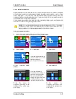
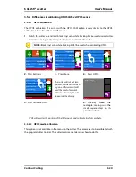
The cutter will make a circular movement while it measures the reflection of the mark color. 

It will briefly display the measured values.  Then it will show a value that is characteristic for 
this media color – mark color combination. Store this value for future reference. 


NOTE:

  An error message may appear if the sensor is not able to differentiate 

between black and white. Make sure that the test has been performed correctly. 

If OPOS is not able to sense the marks, one of the manual alignment methods 

(see 4.3.1.10) should be used.


NOTE:

 If a combination of media color – mark color has already been calibrated 

and recorded, 

 this can be used to enter the value directly, without having 

to re-measure it.


Set

Summary of Contents for S Class 2 OPOS-CAM

Page 1: ...User s Manual Rev 3b...

Page 2: ...o noise for digital apparatus set out in the Radio Interference Regulations of the Canadian Department of Communications Notice Summa reserves the right to modify the information contained in this Use...

Page 3: ...nd Asia Pacific Eastern United States and Latin America Europe Africa and Middle East Summa Inc 10001 Lake City Way NE Seattle WA 98125 USA Main Office 1 206 527 1050 1 800 527 7778 Fax 1 206 527 1046...

Page 4: ...is way you won t have to monitor your cuts even when you re sending through long jobs The S CLASS 2 T series cutters with genuine tangential operation and not simply tangential emulation handle a wide...

Page 5: ...11 1 4 Powering on the cutter 1 12 1 5 Connecting the cutter to a computer 1 13 1 5 1 USB connection 1 13 1 5 1 1 Connecting the S CLASS 2 cutter to a PC using a USB cable 1 13 1 5 1 2 Connecting the...

Page 6: ...c 3 2 3 2 2 OPOS XY 3 3 3 2 3 Printing the graphic 3 4 3 2 4 Orientation 3 5 3 2 5 Registering the marks 3 6 3 2 6 OPOS paneling 3 7 3 3 Calibrating OPOS 3 8 3 3 1 OPOS calibration 3 8 3 3 2 Media cal...

Page 7: ...offset 4 7 4 3 1 6 Pouncing gap 4 7 4 3 1 7 FlexCut 4 7 4 3 1 8 Advanced cutting 4 8 Overcut 4 8 OptiCut 4 9 Paneling 4 9 Panel size 4 9 Panel replot 4 9 Sorting Vectors 4 9 Long Vectors 4 10 TurboCu...

Page 8: ...tangential machine only 5 2 5 1 5 Cleaning the OPOS system 5 3 5 1 6 Changing the fuse 5 4 6 Specs and General Information 6 1 6 1 Introduction 6 1 6 1 1 Product features 6 1 6 2 Specifications 6 3 6...

Page 9: ...17 Pinch roller lever 1 20 1 18 Media flanges 1 20 1 19 Positioning the media flange on the cutter 1 20 1 20 Feeding roll media without using media flanges 1 21 1 21 Media position 1 21 1 22 Pinch rol...

Page 10: ...1 Media sensors S Class 2 cutters 5 1 5 2 Sliding surfaces on Y guide rail 5 2 5 3 Cleaning the OPOS sensor 5 3 5 4 Power entry module 5 4 List of Tables 6 1 S CLASS 2 Cutter specifications 6 3 6 2 S...

Page 11: ...utter make sure there is enough space to assemble the stand and to set the cutter aside in order to insert the stand screws 1 1 1 Removing the packaging from the cutter 1 Remove the straps and the sta...

Page 12: ...ccessories to mount the stand FIG 1 2 1 2 CONTENTS OF THE STAND BOX 2 Mount the horizontal panel between the two legs of the stand with four screws at each side FIG 1 3 1 3 MOUNTING THE HORIZONTAL PAN...

Page 13: ...T 6 Take one of the large c shaped tubes and put it through the front hem in the linen basket Make sure the holes are oriented with the right side upwards so that the tubes click in place securely The...

Page 14: ...out in the leg in order to guide the power cable and data cable If you plan to use these cable guides then put the cables in place before mounting the cutter on the stand 1 1 3 Mounting the cutter on...

Page 15: ...e media stays flat in the middle The outer drive pinch rollers have a selectable pressure the extra rollers in the middle can be enabled or disabled Extra pinch rollers can be added Number of pinch ro...

Page 16: ...s the Optical POSitioning sensor OPOS and a cut off knife to cut a sheet from the roll when a job is finished 6 Cutting strip A self healing orange strip helps avoid any damage to the knife tip when n...

Page 17: ...e is located at the right side of the power entry module Check the specification section to see which fuse is used in the S CLASS 2 cutter WARNING For continued protection against risk of fire replace...

Page 18: ...de 10 Screws to secure the cutter base Screws 3 left and 3 right hold the cutter base on its stand All the screws must be properly secured before using the cutter 11 Tubes for the media basket Tubes i...

Page 19: ...his machine under proper operating conditions without alterations from the original design Any use of the cutter that is beyond the capabilities of the combination knife material is considered as impr...

Page 20: ...the control panel Make sure to observe all the caution labels on the cutter 1 3 2 Operating environment Environmental conditions can significantly affect the machine s performance The environmental c...

Page 21: ...st be installed as part of the branch circuit that supplies power to the wall outlet connected to the cutter The ground conductor must have the same size insulation material and thickness as the groun...

Page 22: ...er entry module at the cutter s rear panel 2 Plug the male end of the AC power cord into a properly grounded wall socket 3 Power on the cutter by pressing the I side of the ON OFF rocker switch which...

Page 23: ...he driver to install 5 Connect one end of the USB cable to a USB port on the computer 6 Connect the other end of the USB cable to the USB port on the back of the cutter 7 Power on the cutter see secti...

Page 24: ...for then follow the below procedure In case the DHCP server is used If no lease time is set the lease time is infinite then no parameters have to be set on the cutter Just connect the cutter and writ...

Page 25: ...ommended to work with a static IP address because cutting software uses a static IP address to send the data to If the lease time of the DHCP server isn t infinite or if no static IP address is used i...

Page 26: ...ies In the newly opened window click on the ping tab Enter the IP address xxx xxx xxx xxx and click on If there is a reply this means that the IP address is in use and cannot be used for the cutter If...

Page 27: ...Tool Tangential knife Media size 50000 x 718 mm Actions Settings Configuration 1 Pause Origin Summa USB port 1 Eth 192 68 1 7 Communication Back Home USB Class Summa USB port 1 Tool commands Accept LA...

Page 28: ...lers are fully raised before sliding them to the left or right Always hold the assembly at the side of the pinch roller to move it from left to right Do not reposition the pinch roller by holding the...

Page 29: ...ad the vinyl when the pinch rollers are set down or when the cutter is switched on A message will appear on the touch screen giving the user time to change the pressure on the pinch rollers NOTE Each...

Page 30: ...FIG 1 18 1 18 MEDIA FLANGES 3 Insert a loosened flange into one end of the media roll and tighten the knob Verify that the flange is secure Then do the same on the other side of the roll 4 Place the f...

Page 31: ...re the front media sensor is covered 2 FIG 1 21 1 21 MEDIA POSITION In circumstances where the above procedure does not work because the media is too narrow to reach the long drive sleeve try position...

Page 32: ...st the drive sleeves The tool carriage will move automatically from the right to the left to sense the usable media width FIG 1 22 1 22 PINCH ROLLER LEVER NOTE It is not recommended to unroll the medi...

Page 33: ...tion while the cutter is not in use The minimal loading procedure consists of A media width measurement The media is unwound over a length equal to the width measured between the outer two pinch rolle...

Page 34: ...e conditions the edges of the vinyl for a given length 4 Press 5 Press or until the required media length appears Then press The cutter will now complete the loading sequence The cutter will come onli...

Page 35: ...manner chosen for entering the needed length of the job the cutter will either load the length or display the chosen length on screen 5 Press The cutter will now complete the loading sequence The cutt...

Page 36: ...to reposition the right Y axis limit origin Then press Two arrows will stay on the screen The tool carriage will move to the left Y axis limit 4 Use or to reposition the left Y axis limit define size...

Page 37: ...Simply turn out the knife see FIG 1 21 yellow arrow clockwise to start cutting Please find the complete description of the knife removal and knife installation below Removing the drag knife 1 Loosen t...

Page 38: ...Turn the holder upside down and tap it lightly on a solid surface to ensure that the knife is completely inserted 4 Slowly turn the knurled knob clockwise until the tip of the blade extends the dista...

Page 39: ...ly scratched the front side of the media backing when the vinyl is removed The blade should never cut in the backing but should only slightly scratch the silicon coating and first few fibers of the ba...

Page 40: ...n pressure NOTE The information on the touch panel shows the tool which was currently selected by the cutter Make sure the cutter s tool setting matches the actual tool in use 1 7 1 3 Pouncing pin ins...

Page 41: ...ure may not control the knife depth The two rollers of the nosepiece should always touch the media thus controlling the knife depth Removing the tangential knife 1 Turn the knife holder counterclockwi...

Page 42: ...osepiece from the side until it snaps into place Gently insert the knife into the tool shaft Hold the nosepiece in place with one hand and with the other hand turn the knife holder counterclockwise un...

Page 43: ...e unchanged Once is pressed the current knife pressure value will be set automatically to the new value and the cutter will cut the knife pressure test pattern FIG 1 33 1 33 KNIFE PRESSURE TEST PATTER...

Page 44: ...utting depth must be readjusted To prevent damage to the cutter check the depth of the knife blade tip and the quality of the cut each time you load a different type of vinyl into the cutter 1 7 2 2 P...

Page 45: ...in use CAUTION Before starting to pounce check whether the pouncing tool is positioned above the black pouncing strip If the pouncing tool is mounted in the rear slot of the clamp the cutting strip w...

Page 46: ...used with standard vinyl max 0 25mm thick 1 Remove the razor blade holder by turning on the knurled screw at the bottom of the tool carriage 2 The razor blade is kept in its place by a small magnet T...

Page 47: ...button symbols can be pressed to change menu items or to change the value for a given submenu parameter FIG 2 1 2 1 TOUCH SCREEN There is also screen saving feature After a certain amount of time the...

Page 48: ...s If there are more than six options for the chosen menu parameter pressing this button will reveal the rest of the options on screen Press to return one step in the menu structure Other buttons that...

Page 49: ...recognized by the group name followed by three points Submenus group certain parameters Access to some of the submenus will be determined by the plotting language or tool type Tests calibration routi...

Page 50: ...S CLASS 2 cutters include 8 user configurations all of which consist of the same parameters Each configuration can have unique parameter settings This allows the cutter to be quickly and easily reconf...

Page 51: ...host computer s application software As soon as any other button on the cutter is pressed the cutter pauses and can no longer be controlled by the host computer However if the computer was busy sendi...

Page 52: ...en or pouncing tool with products from other manufacturers WARNING Each keystroke can initiate an internal test or movement of head or media Keep fingers and other body parts away from the cutting are...

Page 53: ...knives between 0 9 and 0 97 for sandblast knives and between 0 49 and 0 52 for the 60 degree knife Changing the knife offset 1 Power on the cutter load the media and mount the drag knife see section 1...

Page 54: ...to correct problems related to the concentricity of the tangential knife blade NOTE Knife calibration should be done each time the knife is changed and should be checked if the knife shows signs of w...

Page 55: ...e drag knife see section 1 7 2 1 2 Press on Settings 3 Press on Calibrate knife 4 Click on the parameter that needs to be changed The selected parameter will be highlighted in cyan on the touch screen...

Page 56: ...attern 1 and 4 are the most important test patterns They should be as close to perfect as possible Start with the setting of the origin and then set the other parameters Origin correction If the clear...

Page 57: ...d if you obtained a pattern like the one below decrease the value of the longitudinal parameter to correct the closing cut lines However if the test cut resembles the pattern below increase the value...

Page 58: ...e if necessary Press to confirm the chosen knife offset and exit the menu press to leave the knife offset unchanged NOTE Sometimes the cutter feeds the material too fast and the media has no time to s...

Page 59: ...nyl of maximum width and a length that is approximately 1 5 times the width 2 Press Settings 3 Press More 4 Press length calibration The cutter will reload the media and perform the length calibration...

Page 60: ...7 Delete the numbers with the arrow press Apply to confirm the value 8 Press to confirm the value of the measured length TIP Once this user is calibrated change the user name This makes it easy for fu...

Page 61: ...ra instead of the OPOS sensor for registering the OPOS marks Section 3 5 describes the differences between the sensor OPOS and the OPOS CAM 3 2 Basic OPOS operation In general contour cutting includes...

Page 62: ...r software dealer for specifics NOTE Do not place contour lines along the edges of graphics or the slightest movement in the media may result in an unsatisfactory cut Instead practice one of the follo...

Page 63: ...e OPOS Setup to OPOS XY manually on the control panel or via the cutting software NOTE Some cutting software do not support the OPOS XY feature If they also send the alignment command OPOS to the cutt...

Page 64: ...on a roll make sure that the graphic s origin mark coincides with the media s origin 1 1 2 Make sure there is at least a 1cm 0 4in margin on each side of the graphic 2 A 2cm 0 8in margin is preferabl...

Page 65: ...t to landscape the contours and marks will need to be rotated Orientation needed in most cutter software Orientation when using WinPlot Make sure that the cutter is connected to the computer and that...

Page 66: ...need to intervene after the computer has sent the command to start the OPOS job Refer to section 3 4 for these settings Use arrows to maneuver the knife on top of the first mark Press Apply to confirm...

Page 67: ...time NOTE Do not use software paneling when using OPOS paneling Activating OPOS paneling 1 Press Settings 2 Press More 3 Press OPOS 4 Press OPOS paneling 5 Press and then Apply Knife pressure 95 gr Ve...

Page 68: ...re 4 Press OPOS The cutter will cut out a square measuring approximately 9 5x9 5mm and move the square forward Weed out Rectangle will appear on the display 5 Press Calibrate OPOS 6 Carefully weed the...

Page 69: ...e user to choose to either measure the media or to fill in a previously recorded value 5 Press Calibrate media OPOS 6 Press measure The cutter will make a circular movement while it measures the refle...

Page 70: ...bination Store this value for future reference NOTE An error message may appear if the sensor is not able to differentiate between black and white Make sure that the test has been performed correctly...

Page 71: ...subsequent graphics does not require additional user input There are two multiple job situations in which OPOS can be used a When cutting multiple copies of a graphic s on the same media roll b When c...

Page 72: ...computer the cutter will immediately start looking for the mark when it receives an OPOS job from the computer without waiting for the user to move the tool Therefore the user will have to set the too...

Page 73: ...e roll The origin tool can then be set to the left of the media under the OPOS XY line in order to be able to find the origin mark even if it is situated far from the right side of the media OPOS orig...

Page 74: ...USB port 1 Summa USB port 1 Knife pressure 95 gr Velocity 800 mm s Tool Tangential knife Settings Back More Home General Calibrate knife Advanced cutting FlexCut Communication OPOS Settings Back More...

Page 75: ...ut and will come online again 5 Raise the pinch rollers and remove the sheet manually 6 Insert the next sheet into the cutter Lower the pinch rollers NOTE The second and any following sheet must be lo...

Page 76: ...w barcode In this way a complete roll can be cut without intervention of the user Depending on the program barcode server the procedure will have to be started from the control panel of the cutter or...

Page 77: ...ess Unlock OPOSbarcode 5 Set the value to the 6 digit number from the website and press Apply 6 Press Back Knife pressure 95 gr Velocity 800 mm s Tool Tangential knife Media size 50000 x 718 mm Action...

Page 78: ...t the knife under the barcode and press Apply The cutting software will then automatically send the correct cutting data to the cutter The cutter will start sensing the OPOS markers and cut out the jo...

Page 79: ...a in order to determine the position of the printed marks Some software is fully automatic and places the marks sends data to the cutter and processes the camera data Please refer to the user s manual...

Page 80: ...weed the rectangle making sure the small square stays on its place Press Back OPOS will register the position of the little square and calibrate itself accordingly 3 5 2 2 OPOS media calibration This...

Page 81: ...data of the contour lines separately set the cutter in FlexCut mode manually and then send the cut through data Setting the parameters for cutting through the media 1 Press Settings 2 Press FlexCut 3...

Page 82: ...o find the correct balance between cutting deep enough making sure the pieces can be taken out easily and not cutting too deep making sure the material keeps its strength while cutting Sometimes this...

Page 83: ...s also recommended to set the FlexCut parameters on the cutter and not with the cutting software FIG 3 4 3 4 COMBINED CONTOUR CUT AND CUTTING THROUGH Knife pressure 95 gr Velocity 800 mm s Tool Tangen...

Page 84: ...This section can be used as a reference for locating a certain parameter setting or test The less frequently used parameters are also explained in this section 4 2 Action Menu FIG 4 1 4 1 ACTION MENU...

Page 85: ...at the left side of the loaded media 4 2 5 Open file Use this option to cut directly from the USB flash drive or to upgrade the cutter Click on the icon to see the list of the files that are present o...

Page 86: ...S CLASS 2 cutter User s Manual Detailed Operation 4 3 4 2 7 Load The load menu is explained in detail in section 1 6 4 4 2 8 Cut Off This functionality cuts of the currently loaded material...

Page 87: ...S CLASS 2 cutter User s Manual Detailed Operation 4 4 4 3 Configuration Menu FIG 4 2 4 2 CONFIGURATION MENU 1 Depends on the tool setting 2 Not visible if the tool is not a drag knife...

Page 88: ...S CLASS 2 cutter User s Manual Detailed Operation 4 5 FIG 4 3 4 3 CONFIGURATION MENU 3 Only visible if the roll up option is installed...

Page 89: ...media is loaded Press the Velocity button then press the desired velocity to change the velocity Use the up down arrow if the desired velocity is not visible on the screen Press to confirm or to canc...

Page 90: ...re test in between until the minimum knife pressure to cut the material completely through is reached Then increase this value with 5 10 Write down this value Apply Cancel NOTE The pouncing tool is no...

Page 91: ...cut a test pattern Depending on the strength size of the bridges go to step 6 or 7 6 If the bridges are too strong decrease the Flex pressure length and perform the test again 7 If the bridges are to...

Page 92: ...t The value of this parameter is disregarded if paneling is deactivated If this parameter is set at 0 then the cutter will cut each panel only once If it is set at 1 it will cut each panel twice Use t...

Page 93: ...and also detect the end of the media The sensors prevent damage to the cutting strip and knife tip The sensors can be activated or deactivated with this menu When the sensors are activated the cutter...

Page 94: ...ff the operator should manually unroll enough media before starting to cut When autoload is set to ask then the cutter will pause after the pinch rollers are put down This gives the user the time to l...

Page 95: ...lignment methods require that the user registers marks manually using the cutter s keypad Most cutting software can put these marks around the printed graphic automatically X Alignment compensates for...

Page 96: ...or using the windows printer spooler Because of the different USB id s the computer can make a distinction between several cutters attached to it maximum 4 Press the USB Class button and set to the de...

Page 97: ...of the parameter that needs to be changed and use to change the value of the highlighted parameter Press to leave the menu Setting the landing The landing determines among other things the force at w...

Page 98: ...d with black squares When the senor is uncovered almost no black squares will be visible in the rectangle Sensor uncovered Sensor covered FIG 4 5 4 5 SENSOR SETUP The blue stripe in the rectangle is t...

Page 99: ...drive drum may become clogged with accumulated residue from the media liner This may cause the media to slip between the pinch rollers and the drive sleeves thus decreasing traction Cleaning the driv...

Page 100: ...urfaces and on the rollers of the tool carriage Cleaning the sliding surfaces of the Y Guide rail 1 Switch off the machine 2 Take a soft cloth dampened with isopropyl alcohol or mild detergent 3 Clean...

Page 101: ...n tipped swab Cleaning the OPOS system 1 Pull the knife holder upwards 2 Locate the sticker over the hole in the OPOS sensor holder at the left side of the tool carriage 3 Remove the sticker 4 Clean b...

Page 102: ...on against risk of fire replace only with the same type and rating of fuse T2 0A 250V SCHURTER SPT OR EQUIVALENT 1 To remove the fuse 3 lightly pry the fuse holder release clip 2 in the direction oppo...

Page 103: ...h can handle media widths from 170 mm up to 1450 mm 6 7 to 57 The S2 160 which can handle media widths from 170 mm up to 1680 mm 6 7 to 66 6 1 1 Product features Following are the main features of the...

Page 104: ...tic loading of media with optional shuffling to guarantee tracking of longer signs Automatic media pull from roll Media sensing Concatenation and curve smoothing to obtain better cut quality Multiple...

Page 105: ...th 742 29 2 1200 47 2 1350 53 1 1580 62 2 Min margin left right 25 1 25 1 25 1 25 1 Front margin 45 45 45 45 45 45 45 45 Rear margin Sensor on Sensor off 45 33 1 75 1 3 45 33 1 75 1 3 45 33 1 75 1 3 4...

Page 106: ...m x x Standard tangential knife Standard vinyl x 2 Sandblast tangential knife requires special sandblast nose piece Sandblast and thicker soft materials max 1 2 mm x 1 Fiber type plotter type pen Pape...

Page 107: ...Drives USB A receptacle FAT 32 max 8GB and max 100 files Only cut files DMPL and HPGL files or firmware files files with extension summa1 FIG 6 4 6 4 S CLASS 2 INTERFACE SPECIFICATIONS 6 2 5 Firmware...

Page 108: ...m 0 25 mil Accuracy 0 2 of move or 0 25 mm whichever is greater 0 2 of move or 0 010 whichever is greater Knife pressure for drag head 0 to 400 gr Pen pressure for drag head 0 to 400 gr Pouncing pres...

Page 109: ...quisite to obtain high cut quality Additionally media expansion or contraction may occur as a result of temperature variations To improve the dimensional stability of media let it stabilize to the cur...

Page 110: ...Part description Part number Picture Manual and driver CD MD9151 Fuse MF9003 Power cable Regional differences contact local dealer for exact part number USB cable 399 111 Razor blade set of 10 391 146...

Page 111: ...older for drag head 391 332 Standard drag knife 36 set of 5 391 360 60 Blade 1pc 391 231 Drag knife holder for sandblast knife 391 363 Sandblast drag knife 55 set of 5 391 358 Plotter pen set of 5 395...

Page 112: ...ndard tangential knife 36 set of 5 390 534 Sandblast tangential knife 60 390 550 Double sided tangential knife 36 390 551 Double wedge knife 45 1pc 390 560 Insertion tool for tangential knife 390 553...

Page 113: ...piece for ball point 395 330 Tangential pouncing pin holder 395 315 Pouncing pin 391 592 Drag knife holder for tangential head 395 323 Standard drag knife 36 set of 5 391 360 60 Blade 1pc 391 231 FIG...

Reviews: