background image

12

Complete pump overhaul / Dismantling

Dismantle the pump as described in the sections 2-6.

Note!


Oil drainage, mechanical seal and wear plate disman-

tling can wait until cooling jacket is removed.

7.1 

Electrical supply leads

Disconnect all electrical leads from the terminal board / 

contactor in the pump. Then start to remove power and 

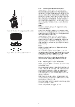
control cables from the pump. (Figure 13)  

J 205:

 The power and control cable are incorporated 

in the top cover and will be removed when cables are 

disconnected from the terminal board /contactor. Re-

move cable clamps prior to unscrewing cable gland 

from cover. Pull out cables. 

J 405:

 Remove cable clamps prior to unscrewing cable 

gland from upper motor part. Unscrew cable gland and 

pull the cable out together with the cable gland.

J 604:

 Remove cable clamps prior to unscrewing nuts 

that hold the cable gland and pull the cable together 

with the cable gland out.
Check the condition of the cable, cable seals and cable 

glands when cover is removed. When a cable seal is 

removed always replace it with a new.

7.2 

Discharge connection

Unscrew the nuts that hold the discharge elbow and 

remove it. (J 604 has a clamping ring holding the dis-

charge connection.) (Figure 13)

7.3 

Cooling jacket 

Make sure all inspection plugs are removed from the 

cooling jacket prior to dismantling cooling jacket.

J 205:

 Lift the pump up in the handle into a vertical 

position with a lifting device and secure it. Put the pump 

standing on the outer longer stud bolts. Place a dis-

tance piece under the diffuser stud bolts (preferably a 

wooden frame at a diameter of the diffuser stud bolts). 

Loosen the stud bolts holding the cooling jacket and lift 

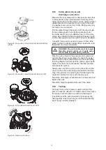
off the cooling jacket from the motor housing. (Figure 

14)

J 405:

 Remove the handle from the pump when it is 

lying down. Thread on an eye bolts on to the shaft end. 

Lift the pump and place it in an upside down position on 

the connection chamber secured by the lifting device. 

Use a dead blow (plastic hammer) to force the cooling 

jacket down until it releases from the motor housing. Lift 

out the complete motor housing and put it lying down. 

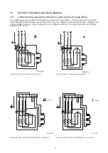
(Figure 15)

J 604:

  Unscrew the lifting eye on top of the pump and 

remove them. Fit an eye-bolt at the end of the shaft and 

use a chain to lift and raise the pump into an upside 

down position standing on the connection chamber. 

Unscrew nuts to release the oil housing from the outer 

jacket. Lift up and withdraw the motor housing and oil 

housing together out of the cooling jacket.(Figure 15) 

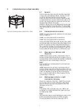
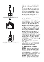
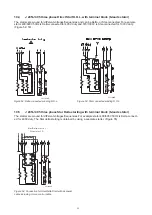
Figure 13: Cable and discharge removal

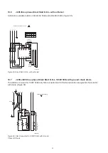
Figure 14: Cooling jacket removal (J 205)

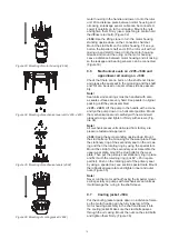
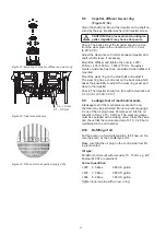
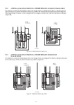
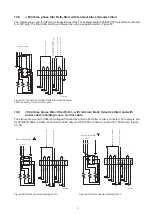
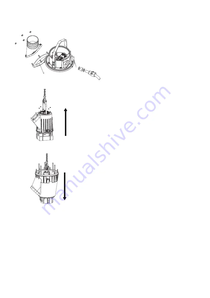
Figure 15: Cooling jacket removal (J 405, J 604)

Summary of Contents for J 205

Page 1: ...en www sulzer com Submersible Drainage Pump J 205 J 405 J 604 Workshop Manual 00831887 02 2020 ...

Page 2: ...antling 12 7 1 Electrical supply leads 12 7 2 Discharge connection 12 7 3 Cooling jacket 12 7 4 Motor housing 13 7 5 Rotor shaft and ball bearings 13 7 6 Wear plate on J 205 and J 405 14 8 Exchange of stator 14 8 1 Removal of stator 14 8 2 Mounting of new stator 15 8 3 Mounting of terminal plate Upper bearing bracket 16 9 Complete pump overhaul Assembly 17 9 1 General 17 9 2 Terminal blocks contac...

Page 3: ...leads stator 25 10 6 J 205 three phase Direct Start D O L with Soft Start 26 10 7 J 205 J 405 three phase Direct Start D O L 1000V 50Hz with ground check diode 26 10 8 J 604 three phase Star Delta Start with terminal block 6 leads stator 27 10 9 J 604 three phase Direct Start D O L with terminal block 6 leads stator and with power cable including 3 core control cable 27 10 10 J 604 three phase Dir...

Page 4: ...quently A reason for inspection could be if a drop in capacity is being noticed 1 2 Repair kits The repair kits includes preselected spare parts which secures a fast and efficient maintenance and avoids unnecessary downtime for the pump For contents of repair kits see spare part lists J 205 00831607 J 405 00831608 J 604 00831609 1 3 Tools Sulzer submersible drainage pumps can be maintained with st...

Page 5: ...ed If the pump has been operating in tough applications additional solvents can be used To clean the pump from lime deposits it is recommended to lower the pump in a bath containing formic acid 15 and 85 water for some hours If needed leave the pump longer Clean the pump again with high pressure water Another example is to use Beto 2000 which is a solvent for concrete deposits 1 6 Recycling in cas...

Page 6: ...est the insulation between cable end plug and earth Note DO NOT MEGGER 1000V PUMPS WITH GROUND CHECK DIODE GC CONNECTED 2 2 Dismantling cover Unscrew the cap nuts screws for the cover Lift off the cover and disconnect the power cables from the contactor terminal block If the water has penetrated through the cable gland the cable seal should be re placed Remove strain relief clamp prior to unscrewi...

Page 7: ...hould also be checked This can be done by measuring the resistance of the phase windings which should give the same reading for all three windings for 3 phase motors For resistance values and wiring dia grams check section 10 Note DO NOT MEGGER 1000V PUMPS WITH GROUND CHECK DIODE GC CONNECTED 2 4 Thermal contacts The circuit with the three built in thermal contacts should by checked for continuity...

Page 8: ...drain of the oil can be done later in the overhaul See sec tion 7 m CAUTION The lifting tackle must always be designed to suit the pump weight TILT THE PUMP OR LAY THE PUMP DOWN IN HORIZONTAL POSITION REMEMBER TO ALWAYS SECURE THE PUMP WITH THE LIFTING CHAIN Drain off the oil into a clean can and examine it If it is clean and contains no water the mechanical seal unit shaft seals are free from def...

Page 9: ...r damage and that the impeller runs free of the wear ring with a clearance of 0 1 0 3mm 0 004 0 012 If not adjust it or if the wear is too high go on with change of impeller Figure 9 Note A drop in capacity due to wear is compensated in a few minutes Just remove base plate and tighten nuts below the wear ring to reestablish a clearance be tween impeller and wear ring of 0 1 0 3 mm 0 004 0 012 Figu...

Page 10: ...must be replaced if it is worn down The wear ring should be replaced if the rubber is worn down to 2 mm 1 16 or is uneven Always re move the key and inspect the shaft seals when chang ing the impeller Assembly Clean the shaft end Mount the impeller on the shaft secured by the key impeller washer and impeller screw Check that the back side of the impeller runs free of the wear plate with a clearanc...

Page 11: ...econdary seal Pull out rotat ing part on secondary seal Remove the stationary ring from the oil casing Figure 12 Assembly J 205 J 405 Grease the shaft end Mount the me chanical seal unit carefully with new and well greased o rings and tighten it firmly with screws J 604 Mount the secondary seal first the stationary ring on the oil casing and then the rotating ring and circlip by using the special ...

Page 12: ...3 Cooling jacket Make sure all inspection plugs are removed from the cooling jacket prior to dismantling cooling jacket J 205 Lift the pump up in the handle into a vertical position with a lifting device and secure it Put the pump standing on the outer longer stud bolts Place a dis tance piece under the diffuser stud bolts preferably a wooden frame at a diameter of the diffuser stud bolts Loosen t...

Page 13: ...oil casing Can be lifted manually or alternatively a lifting strap can be attached to the upper bearing Use a bearing puller to remove both bearings from the shaft Use a long arm puller for the lower bear ing Figure 18 J 405 Lift the rotor unit standing upright and unscrew the lower bearing bracket Remove the upper bearing with a puller and mount a lifting bow on the shaft end and lift out the rot...

Page 14: ...serial no 60400400 For all models When contactor terminal plate upper bearing bracket has been removed together with all cable seals ar range motor cables well folded together to smoothly fol low when the stator is released from the motor housing Put the motor housing on distance pieces Heat the motor housing with two LP gas flames Large propane burner at the stator laminations and down wards unti...

Page 15: ...rease and mount the o ring for the upper bearing in the upper part of the motor housing on J 205 J 604 Figure 22 24 25 Block up the motor housing and make sure that the new stator can be fully lowered into the motor housing Protect the stator insulation from damages and fold stator cables together in two groups and put them into a position so they can easily be pulled up through the holes openings...

Page 16: ...les Grease the o ring on the terminal plate and mount it on the motor housing Figure 26 J 405 Pull the cables through the upper bearing bracket and mount the bracket on the motor housing Mount all cable seals Remember to keep the mark ings on all cables Grease the o ring between the upper bearing bracket and the motor housing Grease and mount the o ring for the upper bearing on the bracket Figure ...

Page 17: ... terminal sections on a DIN rail is used 9 3 Wear plate on J 205 and J 405 Figure 29 J 205 Grease and mount the o ring between the oil casing and wear plate Mount the wear plate on the oil casing and then the stud bolts with washers holding the wear plate Put the unit standing on the studs Note The stud bolts are not fastened so the unit can feel a little unbalanced J 405 Grease and mount the o ri...

Page 18: ...g up wards and place it on a frame which allows enough space to assemble the rotor into the oil casing The cooling jacket turned upside down can be used as sup port frame Mount a lifting bow on the top bearing seat on the shaft then lift the rotor unit and lower it into the bearing seat on the oil casing Heat the bearing seat with LP gas to approx 150ºC 302ºF to easy slip the lower bearing into pl...

Page 19: ...efully with new and well greased o rings and tighten it firmly with screws Fig ure 34 Note All mechanical seal units delivered from factory are pressure tested and approved J 604 Keep the pump standing upside down Mount the stud bolts on the oil casing for the wear plate Place the stationary ring of the secondary seal on the oil cas ing and then the rotating ring by using the special tool Mount th...

Page 20: ...ith a clearance of 0 1 0 3 mm 0 004 0 012 9 9 Leakage test of mechanical seals A leakage test of the mechanical seal and the oil chamber may be performed Mount a pressure gauge in one of the oil plug holes Compress air into the oil chamber of max 0 15 0 20 bar The pressure gauge must be equipped with a closing valve Close the valve and check that the compressed air of 0 15 0 20 bar is maintained i...

Page 21: ...ng jacket can be done manually by two persons and lower it on to the motor housing Note Rotate the motor housing so it s plugs matches the cooling jacket plugs Use a dead blow plastic hammer to force the cool ing jacket down until it fits in place Make sure the stud bolts passes through the holes on the diffuser Mount washers and nuts on the studs Figure 40 Make sure all inner and outer inspection...

Page 22: ...er control cable and mount cable shoes on all cables Connect the power phase leads to the contactor terminal block according to wiring diagram and connect the yellow green earth cable in the main cover connection chamber marked with the earth symbol Grease and mount the o ring on the cover Mount the cover on the pump and arrange the leads so that they may not be jammed or blocking the functioning ...

Page 23: ...he same voltage as the supply voltage Therefore when changing from one voltage to another the contactor must also be changed Figure 46 47 48 49 354010AA Figure 46 Delta connected winding D O L 354009AA Figure 47 Star connected winding D O L 354020 AB L1 L3 FSV 82 A1 A2 1 2 L2 L1 3 2 1 L2 L3 V1 U1 W1 3 5 4 6 V1 U1 W1 W2 U2 V2 2 1 Figure 48 Delta connected winding D O L with FSV 354019 AB V1 U1 W1 V...

Page 24: ... terminal block 12 leads stator The stators are wound for dual voltage and can be changed from one voltage to the other by changing the paral lel connection e g 230V to serial connection e g 460V Figure 51 W1 V1 U1 V2 W2U2 460 V D SERIAL A2 2 1 A1 4 6 3 5 U4 W4 V4 L1 L2 L3 V3 W3 U3 353767 AC A1 A2 230 V DD PARALLEL L1 L3 L2 V3 W3 U3 1 3 5 2 4 6 U4 V4 W4 W1 V1 U1 W2 V2 U2 Figure 50 230 460V 60Hz 12...

Page 25: ...J 205 J 405 three phase Star Delta starting with terminal block 6 leads stator The stators are wound for different voltages frequencies For example stator 400 690V 50Hz is Delta connect ed for 400V duty The Star delta starting is obtained by using a separate starter Figure 55 351183AD Figure 52 Delta connected winding D O L 351182AD Figure 53 Star connected winding D O L Star Delta start or Direct...

Page 26: ... Figure 56 356362AA U2 V1 W1 V2 V1 L1 U1 U1 W1 W2 L2 L3 L1 L2 L3 A1 11 12 T1 T2 T3 A2 13 14 23 24 W2 V2 U2 U1 V1 W1 Thermal Protection Softstarter Thermal Protection Winding INSIDE DELTA CONFIGURATION Orange Black Red Black Orange Red A B C Ramp Up Ramp Down Initial Torque Kick Start A B C C 39 A 2 2 1 Figure 55 Direct Start D O L with soft start 358391AA 2 5 4 1 6 3 V1 W1 U1 U2 V2 W2 Leakage sens...

Page 27: ...CT BRACKET MOISTURE SENS OILCHAMBER THERMAL PROTECTION BEARING UPPER 1 11 12 13 14 2 3 5 51 52 6 WHITE WHITE BLACK RED RED BROWN BROWN BLUE GREEN YELLOW YELLOW W1 5 4 1 U1 W1 V1 U1 V1 3 6 2 W2 V2 U2 W2 V2 U2 F0 F1 DI D2 F3 F4 350535 AD Star Delta starting Figure 57 Connection for Star Delta Start with 2x power cable including 7 core control cable 1 2 5 3 4 6 THERMAL PROTECTION WINDING MOISTURE SEN...

Page 28: ... BEARING UPPER 1 11 12 13 14 2 3 5 51 52 6 WHITE WHITE BLACK RED RED BROWN BROWN BLUE GREEN YELLOW YELLOW Direct on line starting U2 V1 4 1 5 6 2 W1 3 V2 V1 L1 U1 U1 W1 W2 F0 F1 D1 D2 F3 F4 L2 L3 350532AD Figure 60 Delta connected winding D O L 1 2 5 3 4 6 THERMAL PROTECTION WINDING THERMAL PROTECTION BEARING LOWER MOISTURE SENSOR CONNECT BRACKET MOISTURE SENS OILCHAMBER THERMAL PROTECTION BEARING...

Page 29: ...t factor J 205 68A 39A 31A 16A 7 5 J 205 82A 41A 33A 6 0 J 405 66 5A 53 2A 39A 27A 6 9 J 405 136A 82A 68A 54A 7 2 J 604 184A 106A 84A 42A 5 5 J 604 226A 113A 91A 6 0 10 13 Winding resistance Correct readings should be Pumptype 50 Hz 60 Hz Resistance J 205 230 400 V 0 18 ohm 230 460 V 0 68 ohm 400 690 V 460 V 0 50 ohm 500 865 V 575 V 0 79 ohm 1000 V 1 10 ohm J 405 400 690 V 460 V 0 198 ohm 500 865 ...

Page 30: ...30 11 Sectional drawing Tools J 205 ...

Page 31: ...31 J 405 ...

Page 32: ...32 J 604 ...

Page 33: ...0 155 5 O 100 radiecentrum O 80 35 O 98 65 R 2 0 R 2 0 79 radiecentrum 9 5 116 68 133 32 145 60 41 00831650 Tool for lower bearing J 405 SECTION A A A A 9 5 11 90 203 52 15 20 59 43 02 50 75 82 118 125 204 210 O 45 O 58 O 76 O 120 5 O 130 O 50 O 62 O 69 O 76 O 81 68 O 125 45 96 radiec 114radiec R 8 R 1 0 ...

Page 34: ...1 0 O 66 O 84 9 22 37 218 50 O 105 O 61 5 O 80 5 R 1 0 85 radiec 100 5radiec 00831649 Tool for upper bearing J 205 405 A A 6 7 18 25 54 30 57 40 102 111 5 20 25 11 64 01 O 30 O 47 O 62 O 100 5 O 39 O 58 O 78 radiec O 71 34 O 99 83 O 110 5 4 5 R 8 R 1 0 94 5 radiec 78 58 87 84 ...

Page 35: ...4 23 38 32 O 35 O 54 O 74 O 74 O 99 O 119 4 5 13 O 51 O 70 O 98 O 110 3 R 1 0 R 1 0 00831647 Tool for primary seal J 604 SECTION A A A A 8 12 2 84 118 5 136 4 147 147 5 163 5 O 75 9 O 79 7 O 81 95 O 84 95 4 5 4 5 4 5 O 65 4 O 77 5 O 17 5 128 O 3 5 O 49 95 121 52 133 38 ...

Page 36: ...36 00831646 Tool for secondary seal J 604 SECTION A A A A 179 191 207 O 72 4 O 79 2 O 84 9 4 5 4 5 O 17 5 O 47 2 62 6 162 5 171 4 13 191 O 72 25 O 65 00831847 Tool for lifting stator ...

Page 37: ...37 ...

Page 38: ...Sulzer Pump Solutions Ireland Ltd Clonard Road Wexford Ireland Tel 353 53 91 63 200 www sulzer com Copyright Sulzer Ltd 2020 ...

Reviews: