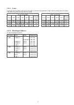
19
motor housing in the handle and lower it onto the rotor
unit. Put a distance piece between motor housing and
oil casing so leakage sensor cable can be connected.
Lower it carefully on to the oil casing. Mount the nuts
and tighten them firmly (use a pipe tong to contra hold
the diffuser stud bolt). (Figure 32)
J 604:
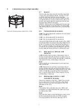
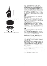
Use the lifting crane to turn the motor housing
standing upside down on the connection chamber.
Mount the stud bolts on the motor housing. Fit an eye
bolt on the impeller shaft end. Lift the rotor unit with oil
casing up and start to lower it into the motor housing.
Grease and mount the o-ring on the motor housing.
Leave a distance between motor housing and oil casing
so the leakage and bearing sensors can be connected.
(Figure 33)
9.6
Mechanical seals on J 205-J 604 and
upper/lower oil casing on J 604
Check that there are no burrs on the shaft end. Clean
and grease the seal seat in the oil casing and the shaft
end. Oil can be used on seal surfaces to ease assem-
bly.
Note!
Seal units and seal rings must be handled with care
as seals surfaces are very hard. Keep seals in original
packing until they are assembled.
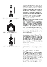
J 205 - J 405:
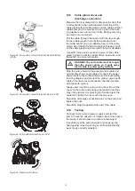
Lift the pump in the handle with a crane
and lye the pump down in a horizontal position. Mount
the mechanical seal unit carefully with new and well
greased o-rings and tighten it firmly with screws. (Fig
-
ure 34)
Note!
All mechanical seal units delivered from factory are
pressure tested and approved.
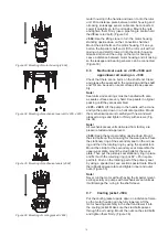
J 604:
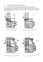
Keep the pump standing upside down. Mount
the stud bolts on the oil casing for the wear plate. Place
the stationary ring of the secondary seal on the oil cas-
ing and then the rotating ring by using the special tool.
Mount the circlip for the secondary seal. Assemble the
upper wear plate, mount the stud bolts for the wear
plate. Then put the primary seal stationary ring in place
and fix it with the retaining ring (pos 82 + 85 in spare
part list). Push on the rotating part of the primary seal
by using a special tool, see section special tools. Mount
the rubberized wear plate and tighten inner and outer
nuts. (Figure 35)
Note!
Never run the motor without having the impeller mount
-
ed. Especially on pumps with mechanical seal units as
it will damage the o-ring in the shaft sleeve
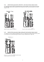
Figure 33: Mounting of motor housing (J 604)
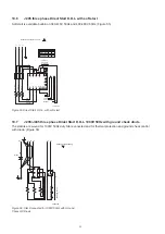
Figure 34: Mounting of mechanical seal unit (J 205, J 405)
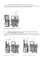
Figure 35: Mounting of mechanical seals (J 604)
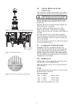
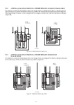
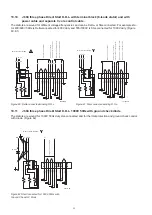
Figure 36: Mounting of cooling jacket (J 604)
9.7 Cooling jacket J 604
Put the cooling jacket upside down on a distance frame
so the motor housing can be fully lowered. Lift the
motor housing assembly in the shaft and lower it into
the cooling jacket. Make sure the stud bolts passes
through the oil casing. Mount the nuts on the stud bolts
and tighten them firmly. (Figure 36)
Summary of Contents for J 205
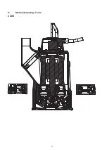
Page 30: ...30 11 Sectional drawing Tools J 205 ...
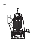
Page 31: ...31 J 405 ...
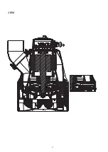
Page 32: ...32 J 604 ...
Page 37: ...37 ...


