Page 7
7-18
#7031931 - Revision A - June, 2014
Component Removal
UNDER COUNTER SERIES
UNDER COUNTER SERIES
(SWS #3603000)
(SWS #3603000)
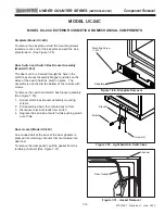
Icemaker Assembly (Model UC-24C)
The icemaker assembly is attached to the right side of
the evaporator cover with screws, two at the top of the
icemaker and one at the bottom.
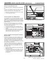
To remove the icemaker assembly, (See Figure 7-43):
1.
Extract icemaker mounting screws.
2.
Pull icemaker forward and to the left, then remove
icemaker head cover.
3.
Disconnect icemaker electrical leads, then pull ice-
maker out of compartment.
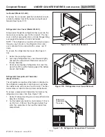
Freezer Air Duct (Model UC-24C)
The freezer air duct is attached to the right side wall
with screws passing through it into screw grommets.
The rear of the air duct has flanges that hook into slots
in the evaporator cover.
To remove the freezer air duct, first remove the icemak-
er assembly, then (See Figure 7-44):
1.
Extract the front mounting screws.
2.
Pull front of air duct toward the left and unhook the
rear flanges from the slots in the evaporator cover.
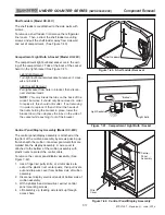
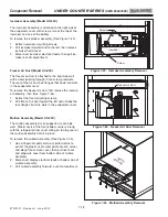
Mullion Assembly (Model UC-24C)
The mullion assembly sits on supports at each side
wall. Plastic rivets at the front bottom corners, along
with the refrigerator liner cover sitting on the top rear of
the mullion assembly hold it in place.
To remove the mullion assembly, (See Figure 7-45):
1.
Use a fingernail, putty knife, or similar device to
extract the plastic rivet center posts at each corner
and along front of wire cover, then pull rivets out
and drop wire cover from bottom side of mullion
assembly.
2.
Disconnect display electrical leads at bottom side of
mullion assembly.
3.
Pull mullion assembly forward, out of compartment.
Figure 7-45. Mullion Assembly Removal
Figure 7-43. Icemaker Assembly Removal
Figure 7-44. Freezer Air Duct Removal
Mullion
Assembly
Screw
Screws
Icemaker
Freezer Air Duct


