Page 9
7-20
#7031931 - Revision A - June, 2014
Component Removal
UNDER COUNTER SERIES
UNDER COUNTER SERIES
(SWS #3603000)
(SWS #3603000)
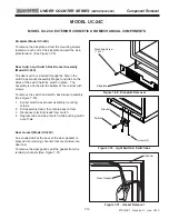
Evaporator Fan Assembly (Model UC-24C)
Screws pass through the rear bracket of the evaporator
fan assembly, as well as the baffle control assembly,
into screw grommet/stand-offs to secure the fan
assembly the back wall.
To remove the evaporator fan assembly, first remove
the mullion assembly, icemaker assembly, freezer air
duct and evaporator cover, then (See Figure 7-49):
1.
Disconnect fan motor electrical leads.
2.
Extract fan assembly mounting screws.
2.
Pull assembly forward, out of compartment.
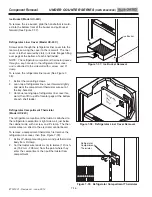
Baffle Control Assembly (Model UC-24C)
Screws pass through the rear bracket of the evaporator
fan assembly and the baffle control assembly, into
screw grommet/stand-offs to secure them to the back
wall.
To remove the baffle control assembly, first remove the
mullion assembly, icemaker assembly, freezer air duct,
evaporator cover and evaporator fan assembly, then
(See Figure 7-50):
1.
Disconnect baffle control assembly electrical leads.
2.
Pull assembly forward, off of screw grommet/stand-
offs and out of compartment.
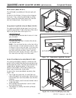
Defrost Heater Assembly (Model UC-24C)
The defrost heater is held to the bottom of the evapora-
tor with heater clips.
To remove the defrost heater assembly, first remove the
mullion assembly, icemaker assembly, freezer air duct
and evaporator cover, then (See Figure 7-51):
1.
Disconnect defrost heater electrical leads.
2.
Extract evaporator mounting screws and pull evap-
orator forward and toward the left.
3.
Slide defrost heater toward the rear of the evapora-
tor.
NOTE:
It may be necessary to remove the defrost
heater clips with a needle-nose pliers in order to
remove the defrost heater.
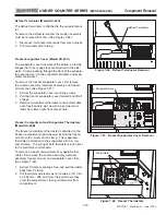
Figure 7-51. Defrost Heater Removal
Figure 7-50. Baffle Control Assembly Removal
Figure 7-49. Evaporator Fan Assembly
Evaporator Fan Assembly
Baffle Control Assembly


