Page 12
7-23
#7031931 - Revision A - June, 2014
MODEL UC-24C SEALED SYSTEM COMPONENTS
NOTE:
To remove any sealed system component from an Under Counter appliance, the appliance must be pulled
from its installation. When removing an Under Counter appliance from its installation, keep in mind that an anti-tip
bracket and a countertop bracket may have been used to make a solid installation.
NOTE:
Before attempting to remove a sealed system
component, evacuate the refrigerant from the sealed
system.
NOTE:
Always replace the high-side filter-drier when
servicing the sealed system.
High-Side Filter-Drier (Model UC-24C)
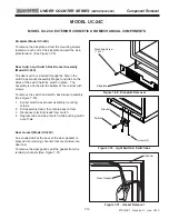
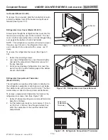
To Remove the filter drier (See Figures 7-56 and 7-57):
1.
Remove access panel from bottom back of unit and
door closer from bottom front corner.
2.
Extract screws securing unit tray to cabinet on the
left side, and loosen screws on right side.
3.
Separate cabinet from unit tray by leaning cabinet
to the right, then insert a spacer between cabinet
and unit tray
(a piece of 2x4 lumber works well).
4.
With the edge of a file, score a line around capillary
tube approximately one (1) inch (25 mm) from filter-
drier outlet.
5.
Fatigue capillary tube at line just scored until it sep-
arates.
6.
With a tube cutter, cut inlet tube approximately one
(1) inch (25 mm) from filter-drier.
NOTE:
Sweating the joints apart is not recommended
as this may induce moisture into the sealed system and
could cause a solder restriction in the capillary tube.
NOTE:
Check the end of the remaining capillary tube
for internal burrs. If burrs exist, rescore a line around
the capillary tube approximately
one (1) inch (25 mm)
from the end and fatigue the capillary tube at this new
line until it separates.
NOTE:
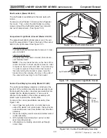
When installing the replacement filter-drier,
insert the capillary tube until it touches the screen, then
pull the capillary tube approximately 3/8” (9.5 mm)
away from the screen before brazing (See Figure 7-58).
When installing a new filter-drier, be sure to thoroughly
clean the tubing before brazing.
Figure 7-57. Drier Removal
Figure 7-56. Unit Tray Component Access
Loosen Screws
on this side
Remove Screws
on this side
Cut here
Cut here
Figure 7-58. Drier Installation
3/8”
(9.5 mm)
Cut-Away
Cut-Away
View of Drier
View of Drier
UNDER COUNTER SERIES
UNDER COUNTER SERIES
(SWS #3603000)
(SWS #3603000)
Component Removal


