Page 13
7-24
#7031931 - Revision A - June, 2014
Component Removal
UNDER COUNTER SERIES
UNDER COUNTER SERIES
(SWS #3603000)
(SWS #3603000)
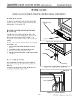
Evaporator (Model UC-24C)
The evaporator is attached to the rear wall with screws,
behind the evaporator cover.
To Remove the evaporator (See Figures 7-59):
1.
Extract screws which hold evaporator to rear wall.
2.
With a file, score a line around capillary tube, 1” (25
mm) or less from evaporator inlet, then fatigue cap-
illary tube at this line until it separates.
4.
With a tube-cutter, cut evaporator outlet 1” (25 mm)
or less from suction line connection point.
NOTE:
Sweating the joints apart is not recommended
as this may induce moisture into the sealed system and
could cause a solder restriction in the capillary tube.
NOTE:
Check the end of the remaining capillary tube
for internal burrs. If burrs exist, rescore a line around
the capillary tube approximately
1” (25 mm)
from the
end and fatigue the capillary tube at this new line until it
separates.
NOTE:
Always replace the high-side filter-drier when
servicing the sealed system.
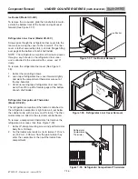
Compressor (Model UC-24C)
The compressor is located at the back of the unit tray.
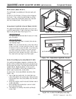
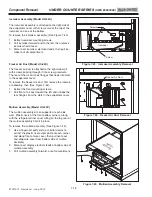
To Remove the compressor (See Figures 7-60 & 7-61):
1.
Remove access panel from bottom back of unit and
door closer from bottom front corner.
2.
Extract screws securing unit tray to cabinet on the
left side, and loosen screws on right side.
3.
Separate cabinet from unit tray by leaning cabinet
to the right, then insert a spacer between cabinet
and unit tray
(a piece of 2x4 lumber works well).
4.
Disconnect compressor electricals.
5.
With a tube-cutter, cut suction tube and discharge
tube approximately 1-1/2" (38 mm) from compres-
sor.
6.
Remove nuts from compressor mounting studs and
lift compressor off of mounting studs.
NOTE:
Sweating the joints apart is not recommended
as this may induce moisture into the sealed system.
NOTE:
Always replace the high-side filter-drier when
servicing the sealed system.
Figure 7-59. Evaporator Removal
Figure 7-61. Compressor Removal
Suction
Discharge
Compressor
Figure 7-60. Unit Tray Component Access
Loosen Screws
on this side
Remove Screws
on this side
Cut


