background image


45 

8.3 Helix test 

 
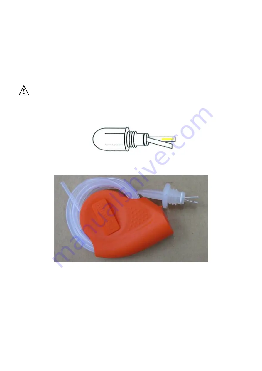
  The Helix test represents a hollow A-type load, i.e. the load with the most critical 
characteristics. 


Carry out the test as follows (Example of TST LOADCHEK STEAM): 


Warning:


TST LOADCHEK STEAM

 is trademark of ALBERT BROWNE LTD., 

 
1.  Place a test strip (Order code : 3783) inside the capsule. 


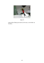
Figure 46 


Figure 47 

2.  Close the capsule. 
3.  Place the test kit on the lower tray in the chamber. 
4.  Select and start B&D cycle at control panel. 
5.  Once the cycle is completed, open the door and remove the test. 

Summary of Contents for SA-300VMA

Page 1: ...Please read manual carefully before using and keep it well SA 300VMA SA 300VMA R Instruction Manual S St tu ur rd dy y A Au ut to oc cl la av ve e S St te er ri il li iz ze er r...

Page 2: ......

Page 3: ...ogram 14 6 1 3 PUMP test BD test PRION 15 6 2 Prepare Sterilization 16 6 3 Standard Sterilization Program 18 6 4 Re Dry Program exclusive either to liquid functions 19 6 5 Liquid Program optional excl...

Page 4: ...2 4 Download 39 7 5 2 5 Printer 39 7 5 2 6 SN 40 7 5 2 7 Cycle 40 7 5 2 8 Exit 40 7 6 Message and troubleshooting for recorder 41 8 Test Instructions 42 8 1 Biological performance of sterilizers 42 8...

Page 5: ...rty damage Caution Please install operate and maintain the sterilizer in accordance with this Instruction Manual Failure to do so could result in serious injury or damage to the unit Warning The outer...

Page 6: ...will illuminate during the sterilization cycle This is part of normal operation and no action on the part of the user is required Warning If the ALARM indicator light illuminates the machine is over p...

Page 7: ...purchased this product European community only Authorised representative in the European community Manufacturer Date of manufacture It is a 6 digit number The first 4 digits represent the year and the...

Page 8: ...move the sterilizer from the packaging base E Check all accessories are present as follows accessories are packed inside the sterilizer chamber Instruction Manual 1 Heater Cover 1 Sterilization basket...

Page 9: ...nmental temperature for installation please refer to 11 Specifications 4 2 Install the sterilizer Caution Please read and follow 5 2 in order to understand the operation of the sterilizer Caution Whil...

Page 10: ...2 B Pipeline installation B 1 Install the water inlet that one end to be fixed at the pipe connector E port And another end must be fixed on the connector of the water source system B 2 Install the e...

Page 11: ...piping in accordance with the local rules or requirements i e only non hazardous liquids may be disposed in public sewage C Install the heater cover as Figure 4 POWER SA 300VMA STURDY STERI STERI ITE...

Page 12: ...16 A 230V AC Warning The plug is one of the measures of emergency cutoff please make sure that the plug is accessible after installation G Press the POWER switch to ON I position the power indicator l...

Page 13: ...d unwrapped items It can also perform sterilization of liquid which is not for medical purpose 5 2 Description of the Sterilizer 5 2 1 External View ST UR DY SA 300 VM A Figure 6 Figure 7 Pressure Gau...

Page 14: ...10 5 2 2 Internal Configuration Figure 8 Over temperature controller Water Level Sensor Heate r Exhaust...

Page 15: ...ed Program Reset Stop Button Reset program while running Press for more than 3 seconds Power Switch ON OFF switch and power indicator Illuminates when ON Process Status Indicator Individual LED light...

Page 16: ...rogram Reset Stop Button Reset program while running Press for more than 3 seconds Power Switch ON OFF switch and power indicator Illuminates when ON Process Status Indicator Individual LED light to i...

Page 17: ...Alarms and COMPLETE indicator will illuminate The Sterilizer goes to STANDBY mode If the COMPLETE indicator did not illuminate repeat the sterilization cycle Select Sterilization Temp 121 C or 134 C S...

Page 18: ...terilization items and close door Standard Sterilization Program Select Liquid Program Button Buzzer Alarms and COMPLETE indicator will illuminate The Sterilizer goes to STANDBY mode If the COMPLETE i...

Page 19: ...rature Sterilization Finishes and Exhaust Starts Buzzer Alarms and COMPLETE indicator will illuminate The Sterilizer goes to STANDBY mode If the COMPLETE indicator did not illuminate repeat the steril...

Page 20: ...cator into the basket as required as Figure 9 Figure 9 Caution Before loading ensure instruments are cleaned and rinsed Warning Refer to 11 Specifications for the maximum permissible load Failure to f...

Page 21: ...17 Warning The door must be closed completely during operation of the unit If the DOOR indicator light illuminates it means that the door is not closed properly ST UR DY SA 300 VM A Figure 10...

Page 22: ...121 C Sterilization Temperature 134 C Unwrapped 22 min 4 min Wrapped 30 min 15 min E Press Dry Timer Button to select a maximum 40 min drying time If drying is required F Press the START Button the se...

Page 23: ...ycle Warning Be careful when removing the sterilized items as the metal surfaces might still be hot Always wear suitable hand protection to remove the box or use the appropriate aids tray holder to li...

Page 24: ...atus Indicator C Press to start Liquid Program The corresponding sterilization time will be Sterilization Time 40 min Sterilization Temperature 121 C Dry Time N A D Press the START button the setting...

Page 25: ...ning the door Warning Beware of steam when opening door after a sterilization cycle Warning Be careful when removing the sterilized items as the metal surfaces might still be hot Always wear suitable...

Page 26: ...es on the three digit display and then the sterilizer will automatically run through the selected program The current progress of the sterilization cycle is indicated by the illuminated LED on the Pro...

Page 27: ...interval between each sterilization cycle to allow the unit to cool 6 7 B D TEST Program A Before start Sterilization program please refer to 6 2 Prepare Sterilization section B How to set the B D TES...

Page 28: ...led and should be run again E Open the door and take out the sterilized items Warning Check the Pressure Gauge is reading ZERO before opening the door Warning Beware of steam when opening door after a...

Page 29: ...lly run through the selected program The current progress of the sterilization cycle is indicated by the illuminated LED on the Process Status Indicator Figure 21 Note The DRY step won t be performed...

Page 30: ...sure vacuum The sterilizer will sound to alert and the Error message E07 will be displayed to notify an emergency operation Please wait till the pressure gauge is reading ZERO or press the Reset Stop...

Page 31: ...g 6 12 1 Sterilization for Implements Place implements on the tray evenly according to Figure 22 Figure 23 Do not pile up nor overlap each implement Figure 22 Figure 23 6 12 2 Glassware Use only heat...

Page 32: ...28 Items should not be allowed to touch the walls of the Chamber as the hot metal can damage the item Figure 24 Loose lid 2 3 full...

Page 33: ...rive before commencing a sterilization cycle Note Microsoft Office Excel are registered trademarks of Microsoft Inc Microsoft is a registered trademark Note A minimum 20 minutes is recommended between...

Page 34: ...2 47 6 0 84 PZ2 019 22 119 6 0 92 019 23 119 6 0 92 S00 036 14 135 8 2 16 036 15 135 8 2 16 S01 037 14 135 5 2 16 037 15 135 5 2 16 S02 038 14 135 6 2 15 038 15 135 6 2 15 038 16 135 5 2 14 Exh 040 20...

Page 35: ...Dry Time 15 m Dry duration Date 2020 03 13 Time 10 45 57 AM Date and Time of sterilization Cycle Counter 24 Cycles that had been started Step Time Temp Pres mmm ss C bar Start 000 00 26 7 0 03 PZ1 H1...

Page 36: ...e finished End end of recording Ster Temp 134 7 136 2 C The maximum and minimum temperature detected during sterilization period Ster Pres 2 12 2 22 bar The maximum and minimum pressure detected durin...

Page 37: ...he first time You can operate on the files in this card in PC via a card reader Data will be stored under the root directory only CAUTION You should backup your storage medium to a safe medium perioda...

Page 38: ...on 1 to move cursor backward 2 to advance digits Decrease button 1 to move cursor forward 2 to decrease digits SET button 1 to set the parameter 2 to confirm adjustment USB port Key Press SET SET SET...

Page 39: ...ure and flashing message Rec will be displayed Figure 28 Note 1 Insert a formatted USB flash drive before commencing a sterilization cycle Note 2 If none of the USB flash drive being detected before c...

Page 40: ...cycle Use a USB flash drive as the storage medium is highly recommended by the manufacturer and always backup your USB flash drive to a secure zone 7 5 1 3 Adjusting mode Press SET button for adjustin...

Page 41: ...econd each time you press the Set button After entering the current Date and Time press Set button returns to the Set manual and then to choose 8 EXIT press Set button again returns to the stand by mo...

Page 42: ...s operation to detach the USB flash drive properly Press SET button in the stand by mode and then press increase or decrease until 3 Remove USB displayed as shown in Figure 35 Figure 35 Press SET butt...

Page 43: ...y mode and then press increase or decrease until 4 Download displayed as shown in Figure 37 Figure 37 Press the SET button then press the increase or decrease to select the file to download as shown i...

Page 44: ...ecrease until the 6 SN shows the machine serial number as shown in Figure 42 Figure 42 7 5 2 7 Cycle Press the SET key in the standby mode and then press the increase or decrease until the 7 Cycle sho...

Page 45: ...st record E108 USB formatter error Re format the USB flash drive Replace another USB flash drive Contact local distributor for service E109 EEPRM fail Replace another USB flash drive Contact local dis...

Page 46: ...units in a horizontal position in the most difficult to sterilize locations and run cycle Warning After sterilization handle unit biological indicator with care Warning Raven ProTest is trademark of...

Page 47: ...th the label facing up After performing the cycle immediately verify the test Being careful while handling the packet It is still hot remove the indicator sheet and follow the instructions given in th...

Page 48: ...heet from the center of the Cube 6 The indicator test sheet should show a uniform color change An incomplete color change may indicate sterilizer malfunction and should be immediately reported to the...

Page 49: ...ample of TST LOADCHEK STEAM Warning TST LOADCHEK STEAM is trademark of ALBERT BROWNE LTD 1 Place a test strip Order code 3783 inside the capsule Figure 46 Figure 47 2 Close the capsule 3 Place the tes...

Page 50: ...IX Test kit will be very hot 6 Open the capsule and remove the test strip 7 Please ask your dealer of HELIX test 8 The result is as follows Incorrect result Figure 48 Incorrect result Figure 49 correc...

Page 51: ...Instructions will adversely affect performance and lifespan of the sterilizer 9 1 Daily Clean the external surfaces with soft cloth Note Use only quaternary disinfectants to clean the units Use of alc...

Page 52: ...lter tap to avoid leakage Figure 51 Figure 52 Take out the filter carefully and flush it with water to clean it Assemble it back as shown in Figure 53 Filter Nut Towel Counterclockwise Take out the fi...

Page 53: ...49 Figure 53 Install the filter following the direction of the arrow Lock the filter nut clockwise...

Page 54: ...e 54 Clean the dirt off at filter of the bottom of the chamber as Figure 54 Caution Clean the dirt off from the sides of the sensor is more important than the tip Use a damp cloth to wipe the surface...

Page 55: ...ring sterilization process Use biological indicators to test the validity of sterilization Check if there s any leakage of the piping Check if the Process Status Indicator lights are functioning norma...

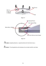
Page 56: ...2 Check if the door gasket frame door gasket plate are installed into the gasket completely as shown in Figure 56 Figure 56 3 Install the gasket with the door gasket frame door gasket plate inside to...

Page 57: ...ward the thick end of the Door Groove Caution The old gasket should be disposed in accordance with the local laws Thick end of Silicone Door Gasket Silicone Door Gasket Door Gasket Frame Door Gasket P...

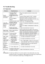
Page 58: ...over one 1 year please follow 7 4 Annually maintenance to replace it Door cannot be opened Pressure persists inside chamber Follow 6 8 to press the Vacuum Release Button and release the pressure Conta...

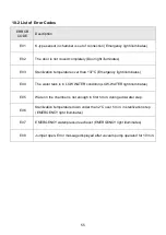
Page 59: ...C Emergency light illuminates E04 The water tank is in LOW WATER condition LOW WATER light illuminates E05 Water in the chamber is not enough in first 5 min during add water step E06 Sterilization te...

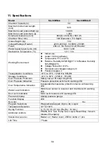
Page 60: ...ree 2 Transportation Conditions 10 C to 70 C 10 RH to 90 RH Storage Conditions 10 C to 50 C 10 RH 70 RH Over Pressure Protection Safety valve 2 55 bar 2 6 kgf cm Over Pressure Indication Pressure prot...

Page 61: ...teral consequential damages or loss This guarantee specifically excludes the expendables and consumable All warranty claims must be directed to the distributors or agents authorized by Sturdy Industri...

Page 62: ......

Page 63: ......

Page 64: ...r Model SA 300VMA SA 300VMA R Manufacturer Sturdy Industrial Co Ltd Address 168 Sec 1 Zhongxing Rd Wugu District New Taipei City 24872 Taiwan EC Representative APEX MEDICAL S L Elcano 9 6 planta 48008...

Reviews: