4T/2T Trigger Control Switch (Ref. 14)
– This switch controls the trigger mode
for the MIG torch trigger. 2T mode the trigger is pulled and held on to activate
the welding circuit, when the trigger is released, the welding circuit stops.
4T is known as ’latching’ mode. The trigger is pulled once and released to
activate the welding circuit, pulled and released again to stops the welding
circuit. This function is useful to longer welds as the trigger is not required to
be held continuously.
LIFT TIG Mode Switch (Ref. 13)
– Lift TIG is an arc ignition system for TIG
welding that removes the need to ‘scratch’ start or strike the tungsten on the
work piece to start the arc, which can have a negative effect on the weld
quality from tungsten contamination. Lift arc starting works by gently touching
the tungsten on the work piece and then lifting it off. The control circuit will
sense when the tungsten is removed from the work piece and send a pulse of
electricity through the torch that will cause the TIG arc to initiate.
Wire Feed (Inching) Switch (Ref. 15)
– Depressing this button will cause the
wire feeder to run at maximum speed without the welding power circuit to be
activated. This is a safe and helpful function for loading wire through the torch
cable prior to welding or when replacing the wire spool.
36V AC Auxiliary Power Supply (Ref. 20)
– May be used to power accessories
that require 36V AC power supply such as 36V heated CO2 regulator (optional
accessory).
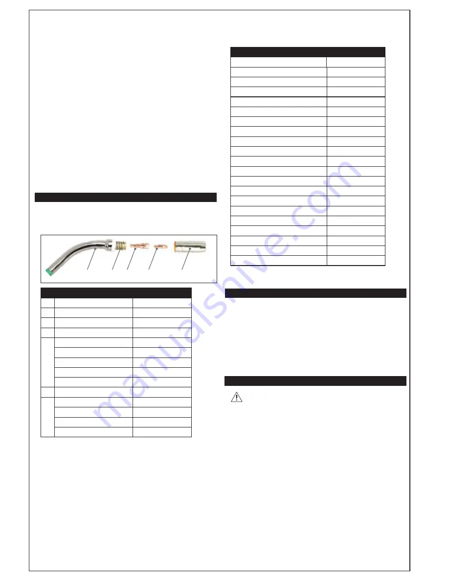
CONSUMABLES & ACCESSORIES
It is very important to recognise that welding torch consumables wear as part
of normal operation and should be replaced in a timely manner. Operating a
torch with worn consumables will cause poor welding results and possible
damage to the torch and machine itself.
1
2
3
4
5
MT250 3m Torch Consumables
No.
Description
Code
1
Swan Neck
MSN2554
2
Shroud Spring
MSS2557
3
Tip Adaptor
MTA2581
4
Contact Tip 0.6mm
MMT2406
Contact Tip 0.8mm
MMT2408
Contact Tip 0.9mm
MMT2409
Contact Tip 1.0mm/0.8mm Alum
007
Contact Tip 1.2mm/1.0mm Alum
MMT2412
5
Conical Nozzle
MCN2570
Wire Liner 0.6-0.9mm Steel 3m
MSL1539
Wire Liner 1.0-1.2mm Steel 3m
MSL2432
Wire Liner 0.6-0.8mm Teflon 3m
MTL1538T
Wire Liner 1.0-1.2mm Teflon 3m
MTL2432T
7KHVHZHDULQJWRUFKFRQVXPDEOHVDQGWKHOLVWRIDFFHVVRULHVIROORZLQJDUH
DOODYDLODEOHIURP\RXUQHDUHVW675$7$VWRUH
Accessories / Consumables
Description
Code
Welding Helmet Professional
':
Professional Welding Gloves
$:*
Argon Regulator
*5$5
MIG Welding Tip Dip Gel 120g
7'
Welding Magnet - 5"
:0*
MIG Wire 0.6mm Mild Steel, 5kg
MW5KG06
MIG Wire 0.8mm Mild Steel, 5kg
0:.*
MIG Wire 0.8mm Flux Cored, 5kg
0:.*)&
MIG Wire 0.8mm Mild Steel, 15kg
0:.*
MIG Wire 0.9mm Mild Steel, 15kg
MW15KG09
MIG Wire 1.0mm Mild Steel, 15kg
MW15KG10
Spool Gun 6m
SP100N
WP17 Valve TIG Torch 4m
TWP17-12-2D
WP26 Valve TIG Torch 4m
TWP26-12-2
1.0/1.2 mm 'U' Groove Drive Roller
WT 48DRU
0.8/1.0 mm 'V" Groove Drive Roller
WT 49DRV
0.8/0.9mm Knurled Groove Drive Roller
WT78DRK
0.6/0.8mm 'V' Groove Drive Roller
WT80DRV
MB15 MIG torch 3m (Euro)
MT150-3E
MB25 MIG torch 3m (Euro)
MT250-3E
)RUDOORWKHUVSDUHSDUWVDQGDFFHVVRULHVSOHDVHFRQWDFW\RXU
ORFDO675$7$VWRUH
WELDER INSTALLATION
(OHFWULFDO&RQQHFWLRQ
7KH
;0352
LVGHVLJQHGWRUXQRQDVWDQGDUG$9$&SRZHUVXSSO\
,IDQH[WHQVLRQFRUGPXVWEHXVHGLWVKRXOGEHQRORQJHUWKDQPDQGEHD
KHDY\GXW\LQGXVWULDO$YHUVLRQZLWKDPLQLPXPFDEOHFRUHRIPP
2SHUDWLQJ(QYLURQPHQW
$GHTXDWHYHQWLODWLRQLVUHTXLUHGWRSURYLGHSURSHUFRROLQJIRUWKH
;0352
(QVXUHWKDWWKHPDFKLQHLVSODFHGRQDVWDEOHOHYHOVXUIDFHZKHUHFOHDQFRRODLU
ZLOOHDVLO\
n
RZDFURVVWKHXQLW7KH
;0352
KDVHOHFWULFDOFRPSRQHQWVDQG
FRQWUROFLUFXLWERDUGVZKLFKZLOOEHGDPDJHGE\H[FHVVLYHGXVWDQGGLUWDFOHDQ
RSHUDWLQJHQYLURQPHQWLVHVVHQWLDO
MIG WELDING SET UP & OPERATION
DANGER
Before adjusting the feed roller or wire spool, ensure that the
mains power is switched off.
1. Fitting Wire Spool
Open the wire spool cover. Unthread the wire spool retainer. Fit the wire spool
to spool holder shaft, ensuring that the wire exits towards the bottom.
Set the spool brake tension by adjusting the spool tension adjustment nut
before replacing the wire spool retainer. The spool brake tension should be
set so that the spool can rotate freely, but does not continue to rotate once
the wire feed stops. This may need to be adjusted as the wire is used and the spool
weight decreases.
CAUTION:
Excessive spool brake tension will cause wire feeding issues and affect
welding performance as well as contribute to premature failure/ wear of wire feed
components.
Feed the wire from the spool through the Wire Drive Inlet Guide (24) into the
wire feeder.
Release the Wire Feed Tension Arms (25) by pivoting the Wire Feed Tension
Adjustment Lever (26) from the vertical to the horizontal position.
Check that the groove type of the Wire Drive Rollers (27) match the selected
MIG wire type and size. Each pair of drive rollers have two different sized grooves;
the size of the groove in use is stamped on the side of the drive roller.
ZZZVWUDWDFRQ]


