Chapter 3. Installation and Operation of the SWXTL-BT Tabletop Tape Drive
3–4
Order Number: EK–SM1TB–UG. E01
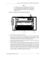
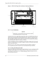
Figure 3–1 SWXTL-BT Tape Drive Front Panel Controls and Indicators
4. Load a cassette tape into the drive (refer to Figure 4–3) and observe the T
APE IN
U
SE
in-
dicator. The indicator initially should blink momentarily at 1-second intervals after the
handle is closed (pushed down) as the tape drive engages the tape, then double-blink at
the same interval while the tape is being moved to the correct position. Depending on
whether this is a new tape or a tape with some previously recorded data, this blinking
period should extend from 20 seconds to a few minutes after the cassette is loaded, until
the tape has reached the applicable position for recording new data, after which the T
APE
IN
U
SE
indicator should remain steadily on.
5. After the unit passes POST, connect the unit to your host computer through appropriate
SCSI interface cables, as follows. If applicable, have your system administrator assign a
device name to the drive.
NOTE
If you are connecting the tabletop tape drive to a fast, single-
ended SCSI bus, the interface cable cannot exceed three meters
(9.8 feet). If you are connecting the tape drive to a slow, single-
ended SCSI bus, the interface cable can be up to 6 meters (19.7
feet) in length. Table 3–1 provides part-number identifications for
ordering appropriate cables.
a. Connect the appropriate 50-pin-connector end of the SCSI cable to either of the
two vertically oriented jacks at the upper right rear of the tape drive unit.
b. If this tape drive is the last unit on the SCSI bus, make sure that the supplied
terminator is securely fastened in place in the adjacent connector.


