Order Number: EK–SM1TB–UG. E01
4–1
4
Controls, Indicators, and Operation of the
10/20 GB DLT Cartridge Tape Drive
This chapter identifies the switches and LED indicators on the front panel of the 10/20-GB DLT Cartridge Tape
Drive, describes how to use them (including operation of the power-on self-test (POST), provides use rules for
the CompacTape III cartridge data and cleaning tapes, gives detailed procedures for correct loading and un-
loading of the tape cartridges, and explains how to select a desired density format for recording.
4.1
General
Digital’s 10/20-GB-family of DLT Tape Drives offer outstanding performance and integrity,
combined with ease of use. All normal-use operator controls are mounted on the front panel,
consisting of two push-button switches, a pull-down handle, and several color-differentiated
LED indicators to indicate operational status at any given time. The drive uses these indica-
tors to “report” when the unit is ready for a tape, data format of the tape currently mounted,
when the heads need to be cleaned, and when it is safe to take a tape out of the drive, as well
as whether or not the tape cartridge currently is write-protected.
4.2
Front-Panel Controls and Indicators
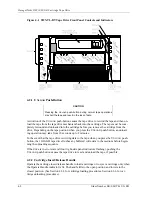
All operating controls are located on the front panel (refer to Figure 4–1).
The cartridge insert/release handle provides simplified tape loading and unloading proce-
dures, printed on the handle. This handle must be pulled down in order for a tape cartridge to
be loaded or removed, as described in the following procedures, but must not be pulled down
unless the green O
PERATE
H
ANDLE
indicator is lit.
The right-side front panel of the tape cassette drive contains four indicators (W
RITE
P
ROTECTED
, T
APE IN
U
SE
, U
SE
C
LEANING
T
APE
, and
O
PERATE
H
ANDLE
LEDs) and one
push-button switch (U
NLOAD
push-button).
Table 4–1 identifies each of these indicators/controls and gives the operating condition and
function of each one.
The left-side front panel of the tape cassette drive contains five indicators (TK85, TK86,
TZ87, C
OMPRESS
, and D
ENSITY
O
VERRIDE
LEDs) and one push-button switch (D
ENSITY
S
ELECT
push-button). Table 4–2 identifies each of these indicators/controls and gives the
operating condition and function of each one.


