Chapter 4. Controls, Indicators, and Operation of 10/20-GB DLT Cartridge Tape Drive
Order Number: EK–SM1TB–UG. E01
4–5
performed with the host system power on (if your operating system permits) or off, and with
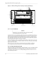
the SCSI bus connected or disconnected. (Refer to Figure 4–1 for the locations of the front
panel LED indicators on the drive.)
NOTE 1
The description of indicator sequence described in this procedure,
as in the associated tables, describes what happens when the
10/20-GB unit is connected to an active SCSI bus. If the SCSI bus
is not connected, all left-side panel indicators remain on at all
times that power is applied to the unit.
To execute POST, proceed as follows:
NOTE 2
If the W
RITE
-P
ROTECTED
indicator flashes orange and the T
APE IN
U
SE
indicator flashes yellow continuously for more than 30 sec-
onds in the POST exercise, then the test has failed. Repeat the
test to clear the failure (power off and then on). If the test still fails,
replace the drive.
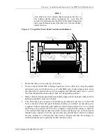
1. Power on the tape drive (if you are using the tabletop unit, depress top “1” portion of 1/0
rocker switch on the rear panel; if you are using an SBB mounted in a storage pedestal,
turn on pedestal power or else pull the SBB tape drive out and then push it back into
place).
2. Observe that all left-side panel indicators initially light, with all right-side indicators then
lighting sequentially, from top to bottom.
If the SCSI bus is not connected, all left-side panel indicators will stay lit; if the SCSI
bus is connected, all left-side panel indicators should go out within 1 second after power
is applied, while all right-side panel indicators should remain lighted for 3 to 5 seconds
and then go out except for T
APE IN
U
SE
indicator, which continues to blink for a few
seconds while tape mechanism searches for tape. Subsequent indicator activity depends
on whether or not a tape cartridge currently is mounted in the tape drive, as defined in
Table 4–3. (If no tape is present, the T
APE IN
U
SE
indicator continues to blink until the
applicable point for recording new data is under the recording head, at which time that
indicator becomes steadily lit; if no cartridge is mounted, the Tape in Use indicator goes
out, a transducer inside the unit beeps to alert you, and the green O
PERATE
H
ANDLE
indicator becomes steadily lit to indicate that the door latch is released and that you can
pull up the cartridge insert/release handle to allow insertion of tape.)
Following initialization, the drive is in one of the four states defined in Table 4–3.
NOTE
Under normal conditions, you should not power up a tape drive
with a tape cartridge mounted, so that only conditions a and d in
Table 4–3 would apply. The two intervening conditions, describing
situations in which a tape was already mounted before power was
applied, are included to cover emergency situations.


