StorageWorks DLT 10/20 GB Cartridge Tape Drive
4–6
Order Number: EK–SM1TB–UG. E01
Table 4–3 Operating States of 10/20-GB DLT Cartridge Tape Drive Unit
Following Initialization
Starting Condition
Status Light Sequence
a.
If no tape cartridge is
mounted in drive and the
drive passes POST:
(1)
The yellow T
APE IN
U
SE
light turns off.
(2)
The internal audio-transducer alarm beeps.
(3)
The green O
PERATE
H
ANDLE
light turns on.
(4)
The handle is unlatched.
You can now raise the handle and insert a tape car-
tridge into the drive.
b.
If a cartridge is present in
the drive and the cartridge
insert/release handle is
down.1
(1)
The drive loads the tape cartridge.
(2)
The yellow T
APE
-
IN
-U
SE
light blinks while the
tape is mounting and then lights steadily.
(3)
The left-side indicator corresponding with the
last-written density format of the current tape
cartridge lights.
(4)
The D
ENSITY
O
VERRIDE
blinks.
(5)
You can now select a density (refer to Section
4.7.1); the drive is ready for use.
c.
If a cartridge is present in
the drive and the cartridge
insert/release handle is up.
2
(1)
The yellow T
APE IN
U
SE
light turns off.
(2)
The internal audio transducer beeps.
(3)
The green O
PERATE
H
ANDLE
light flashes.
When you lower the handle, the cartridge loads.
d.
If the drive detects an error
condition.
All right- or left-side lights blink repeatedly.
Try to unload the tape and reinitialize the drive by
pressing the Unload push-button or by turning drive
power off and then on again (or, if you have an SBB,
by hot-swapping that unit). If you do this, the right- or
left-side lights stop blinking and the drive tries to
reinitialize; if the attempt succeeds, the lights mo-
mentarily turn on steadily again and then go off.
1
Not recommended. Shutting down power while a tape cartridge is still mounted in the
drive can result in damage either to the tape cartridge (and/or its data) or to the drive,
itself.
2
Not recommended.
4.4
Status Indication of Tape Drive LEDs
The status of the tape drive under different conditions is indicated by the W
RITE
P
ROTECTED
and T
APE IN
U
SE
LEDs. In the normal operating state, the W
RITE
P
ROTECTED
LED only
indicates the write-protect status and the T
APE IN
U
SE
LED only indicates the drive activity
and load status. Table 4–4 describes the status conditions represented by the LEDs. Refer to
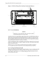
Figure 4–1 to identify the LEDs on the front panel.


