background image

54

Chapter 7

 Configuring Routing and Installing Policies

Adding the Default Route

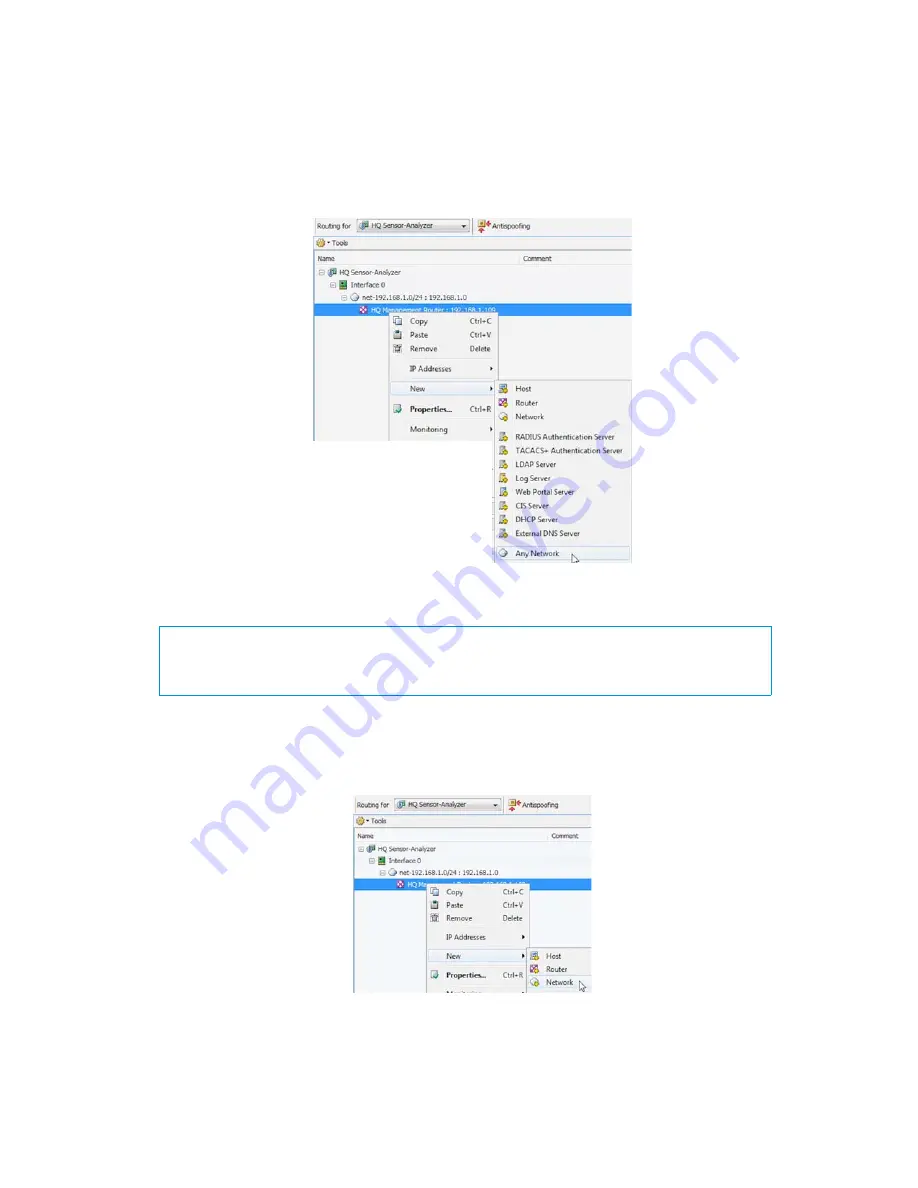
To add the default route

Right-click the Router and select 

New

Any Network

.

You are not actually creating a new element, just inserting the existing default element “Any 
Network”.

Adding Other Routes

To add other routes

1.

Right-click the Router and select 

New

Network

. The Network Properties dialog opens.

2.

Give the network a unique a 

Name

 and enter the network space.

What’s Next?

To add other routes, proceed to 

Adding Other Routes

.

Otherwise, proceed to 

Installing the Initial Policy

 (page 55).

Summary of Contents for stonegate 5.2

Page 1: ...STONEGATE 5 2 INSTALLATION GUIDE INTRUSION PREVENTION SYSTEM...

Page 2: ...described in these materials are provided pursuant to the general terms for support and maintenance services and the related service description which can be found at the Stonesoft website www stones...

Page 3: ...ONFIGURING SENSORS AND ANALYZERS CHAPTER 5 Defining Sensors and Analyzers 31 Getting Started with Defining Sensors and Analyzers 32 Creating Engine Elements 32 Defining System Communication Interfaces...

Page 4: ...77 Obtaining Installation Files 77 Upgrading or Generating Licenses 78 Upgrading Licenses Under One Proof Code 78 Upgrading Licenses Under Multiple Proof Codes 79 Installing Licenses 80 Checking the...

Page 5: ...5 INTRODUCTION In this section Using StoneGate Documentation 7...

Page 6: ...6...

Page 7: ...ibes how to use the StoneGate IPS Installation Guide and lists other available documentation It also provides directions for obtaining technical support and giving feedback The following sections are...

Page 8: ...ate important or additional information Tip Tips provide additional helpful information such as alternative ways to complete steps Example Examples present a concrete scenario that clarifies the point...

Page 9: ...scenarios for each feature area Available for StoneGate Management Center Firewall VPN and StoneGate IPS Installation Guide Instructions for planning installing and upgrading a StoneGate system Avail...

Page 10: ...Stonesoft Corporation visit our website at http www stonesoft com Licensing Issues You can view your current licenses at the License Center section of the Stonesoft website at https my stonesoft com...

Page 11: ...11 PREPARING FOR INSTALLATION In this section Planning the IPS Installation 13 Installing IPS Licenses 19 Configuring NAT Addresses 23...

Page 12: ...12...

Page 13: ...e installation can begin The chapter also includes an overview to the installation process The following sections are included Introduction to StoneGate IPS page 14 Example Network Scenario page 14 Ov...

Page 14: ...r Ethernet layer 2 traffic The main features of StoneGate IPS include Multiple detection methods misuse detection uses fingerprints to detect known attacks Anomaly detection uses traffic statistics to...

Page 15: ...llation Before you start the installation you need to carefully plan the site that you are going to install Consult the Reference Guide if you need more detailed background information on the operatio...

Page 16: ...etwork wire between network devices The capturing is done passively so it does not interfere with the traffic With a network TAP the two directions of the network traffic is divided to separate wires...

Page 17: ...any fixed setting Gigabit standards require interfaces to use autonegotiation fixed settings are not allowed at gigabit speeds Inline interfaces of sensors require additional consideration since the s...

Page 18: ...18 Chapter 2 Planning the IPS Installation...

Page 19: ...s chapter instructs how to generate and install licenses for sensors and analyzers The following sections are included Getting Started with IPS Licenses page 20 Generating New Licenses page 20 Install...

Page 20: ...sensors and analyzers 1 Generate the licenses at the Stonesoft website See Generating New Licenses page 20 2 Install the licenses in the Management Client See Installing Licenses page 21 Generating N...

Page 21: ...nstall Licenses 2 Select one or more license files in the dialog that opens To check that the licenses were installed correctly 1 Click the Configuration icon in the toolbar and select Administration...

Page 22: ...enses you must bind them manually to the correct engines once you have configured the engine elements What s Next If NAT is applied to communications between system components proceed to Configuring N...

Page 23: ...tact addresses when a NAT network address translation operation is applied to the communications between the sensor or analyzer and other StoneGate components The following sections are included Getti...

Page 24: ...Locations In the example scenario above a Management Server and a Log Server manage StoneGate components both at a company s headquarters and in a branch office NAT could typically be applied at the f...

Page 25: ...s See Defining Sensors and Analyzers page 31 Defining Locations The first task is to group the system components into Location elements based on which components are on the same side of a NAT device T...

Page 26: ...dress for each Location This allows you for example to define a contact address for each Internet link in a Multi Link configuration for remotely managed components To define the Management Server and...

Page 27: ...Contact Address es are not valid from all other Locations Close the server properties and define the contact addresses for other servers in the same way Note Elements grouped in the same Location elem...

Page 28: ...28 Chapter 4 Configuring NAT Addresses...

Page 29: ...29 CONFIGURING SENSORS AND ANALYZERS In this section Defining Sensors and Analyzers 31 Saving the Initial Configuration 45 Configuring Routing and Installing Policies 51...

Page 30: ...30...

Page 31: ...nagement Client so the engines cannot be successfully installed before defining them in the Management Center as outlined in this chapter The following sections are included Getting Started with Defin...

Page 32: ...interface numbering on the engines However if you do the engine s initial configuring using the automatic USB memory stick configuration method the Interface IDs in the Management Center are mapped t...

Page 33: ...nents More than one system communication interface can be added to provide a primary and a backup interface for Management Server communications For Analyzers the volume of log traffic can easily grow...

Page 34: ...ace Properties dialog opens 3 Select the Interface ID 4 Not applicable to Analyzers Select Normal Interface as the Type 5 Click OK The physical interface is added to the interface list Add the necessa...

Page 35: ...VLAN ID is added to the physical interface Repeat the steps above to add further VLANs to the interface The VLAN interface is now ready to be used as a network interface The VLAN interface is identif...

Page 36: ...v4 Address Repeat for each node if this is a Sensor Cluster element 3 Enter the Netmask 4 If NAT is applied to system communications double click the Contact Address cell and continue as explained in...

Page 37: ...define several IP addresses for the same physical network interface Before you continue write down the networks to which each Interface ID is connected Setting Interface Options for IPS Engines Interf...

Page 38: ...can send TCP resets and ICMP destination unreachable messages when the communications trigger a response You can use a system communications interface for sending resets if the resets are routed corre...

Page 39: ...nterfaces except that the same Logical interface cannot be used to represent both capture interfaces and inline interfaces on the same Sensor The rules in the ready made IPS Strict Template and IPS Sy...

Page 40: ...t VLAN is selected automatically An interface you want to use as the reset interface must not have any manually added VLAN configuration The reset interface must be in the same broadcast domain as the...

Page 41: ...se restrictions regarding this interface type External equipment must be set up to mirror traffic to the capture interface You can connect a capture interface to a switch SPAN port or a network TAP to...

Page 42: ...n network cards have fixed pairs of ports Take particular care to map these ports correctly during the initial configuration of the engine Otherwise the network cards do not correctly fail open when t...

Page 43: ...fault inline sensors inspect all connections If the traffic load is too high for the inline sensor to inspect all the connections some traffic may be dropped Alternatively inline sensors can dynamical...

Page 44: ...tion 1 Write down the networks to which each Interface ID is connected 2 Click OK close the engine properties The following notification opens 3 Click No What s Next You are now ready to transfer the...

Page 45: ...configuration in the Management Center and how to transfer it to the physical sensor and analyzer engines The following sections are included Configuration Overview page 46 Saving the Initial Configur...

Page 46: ...ers and triggers the creation of one time passwords needed to establish a connection with the Management Server There are three ways to initialize your IPS engines and establish contact between them a...

Page 47: ...ration Wizard you can Enable SSH Daemon and select the Local Time Zone and Keyboard Layout 4 Sensors only Click Select and select the appropriate policy if you already have a policy you want to use Th...

Page 48: ...it 5 Click Close Once the sensor or analyzer is fully configured the SSH daemon can be set on and off using the Management Client Enabling SSH in the initial configuration gives you remote command lin...

Page 49: ...iance see the installation and initial configuration instructions in the Appliance Installation Guide that was delivered with the appliance After this return to this guide to set up basic routing and...

Page 50: ...50 Chapter 6 Saving the Initial Configuration...

Page 51: ...the engine s and the Management Server the engines are left in the initial configuration state Now you must define basic routing and policies to be able to use the engines to inspect traffic Both of...

Page 52: ...the Sensor or Analyzer if the networks cannot be reached through the default gateway Routing is most often done using the following elements Network elements represent a group of IP addresses Router...

Page 53: ...to add other routes you must first add a Router element to represent the gateway devices that forward packets to the networks To add a router 1 Right click the Network and select New Router The Router...

Page 54: ...ing a new element just inserting the existing default element Any Network Adding Other Routes To add other routes 1 Right click the Router and select New Network The Network Properties dialog opens 2...

Page 55: ...e cannot be edited directly See the IPS Reference Guide for more information on the predefined policies and templates When you install a policy on a sensor the analyzer that the sensor uses also recei...

Page 56: ...l task dialog opens 3 Select the engine s 4 Click Add The selected engines are added to the Target list Note The Strict Policy and the System Policy contain a rule that uses the Terminate action for a...

Page 57: ...u install a policy all the rules in the policy as well as all the IPS engine s other configuration information including interface definitions and routing information are transferred to the engines Co...

Page 58: ...ttom of the window 3 Use the Commands menu to command sensors Online Offline Only sensors in Online mode process traffic Analyzers do not have a corresponding command they always process the event inf...

Page 59: ...59 INSTALLING SENSORS AND ANALYZERS In this section Installing the Engine on Intel Compatible Platforms 61...

Page 60: ...60...

Page 61: ...S Sensors and Analyzers on standard Intel or Intel compatible platforms such as AMD The following sections are included Installing the Sensor or Analyzer Engine page 62 Obtaining Installation Files pa...

Page 62: ...Configure the engines and establish contact with the Management Server See Configuring the Engine page 64 Obtaining Installation Files Downloading the Installation Files 1 Go to the download page at t...

Page 63: ...make sure you have the initial configuration or a one time password for management contact for each sensor and analyzer engine These are generated in the Management Center See Saving the Initial Confi...

Page 64: ...are mapped to physical interfaces in sequential order Interface ID 0 is mapped to eth0 Interface ID 1 is mapped to eth1 and so on To install and configure the engine with a USB stick 1 Make sure you...

Page 65: ...ENTER Proceed to Configuring the Operating System Settings page 65 To import the configuration 1 Select Floppy Disk or USB Memory and press ENTER 2 Select the correct configuration file for this engi...

Page 66: ...engine s clock is automatically synchronized with the Management Server s clock To set the rest of the OS settings 1 Type in the name of the engine 2 Type in the password for the user root This is the...

Page 67: ...rface to run the network sniffer on that interface 3 Highlight the Mgmt column and press the spacebar to select the interface for contact with the Management Server 4 Optional sensors and sensor analy...

Page 68: ...tion is automatically filled in Activating the Initial Configuration Before the engine can make initial contact with the Management Server you activate an initial configuration on the engine The initi...

Page 69: ...engine type 1 Select the type of engine using the arrow keys and the spacebar 2 Highlight Finish and press ENTER The engine now tries to make initial Management Server contact If you see a connection...

Page 70: ...te IPS Sensor or Analyzer as explained in Table 8 1 The partitions are allocated in two phases First disk partitions are created and second the partitions are allocated for their use purposes To parti...

Page 71: ...partition type 2 For the swap partition type 5 For the data partition type 6 For the spool partition type 7 3 Check the partition allocation and type yes to continue The engine installation starts 4 W...

Page 72: ...72 Chapter 8 Installing the Engine on Intel Compatible Platforms...

Page 73: ...73 UPGRADING In this section Upgrading 75...

Page 74: ...74...

Page 75: ...here is a new version of the sensor and analyzer engine software you should upgrade as soon as possible The following sections are included Getting Started with Upgrading page 76 Upgrading or Generati...

Page 76: ...d is not changed in an upgrade or a rollback Although parts of the configuration may be version specific for example if system communications ports are changed the new version can use the existing con...

Page 77: ...are several third party programs available To manually download an engine upgrade file 1 Download the installation file from www stonesoft com download There are two types of packages available The z...

Page 78: ...ode contains the license information for several components You can also always use the multi upgrade form to upgrade the licenses see Upgrading Licenses Under Multiple Proof Codes page 79 To generate...

Page 79: ...oof Codes If you have several existing licenses with different POL codes that you need to upgrade you can make the work easier by generating the new licenses all at once To upgrade multiple licenses 1...

Page 80: ...e Stonesoft License Center website using the multi upgrade form and submit the form with the required details The upgraded licenses are sent to you You can view and download your current licenses at t...

Page 81: ...ion icon in the toolbar and select Administration The Administration Configuration view opens 2 Expand the Licenses branch and select IPS You should see one license for each analyzer and sensor engine...

Page 82: ...lso create a scheduled Task for the remote upgrade as instructed in the Online Help During a Sensor cluster upgrade process it is possible to have the upgraded nodes online and operational side by sid...

Page 83: ...5 Select whether you want to transfer the upgrade for later activation or both transfer and activate now 6 Check the node selection and change it if necessary 7 Check the Engine Upgrade file and chan...

Page 84: ...ng a monitor and keyboard or a serial cable During a Sensor cluster upgrade process it is possible to have the upgraded nodes online and operational side by side with the older version nodes Upgrading...

Page 85: ...the engines have two partitions When an engine is upgraded the inactive partition is used When the upgrade is finished the active partition is switched The earlier configuration is kept on the inacti...

Page 86: ...wo partitions When an engine is upgraded the inactive partition is used When the upgrade is finished the active partition is switched The earlier configuration is kept on the inactive partition If the...

Page 87: ...87 APPENDICES In this section Command Line Tools 89 Default Communication Ports 95 Example Network Scenario 101 Index 107...

Page 88: ...88...

Page 89: ...d line tools available on StoneGate IPS engines For instructions on how to access the command line see the Administrator s Guide or the Online Help of the Management Client The following sections are...

Page 90: ...eters see below or use the i option to import parameters from a file del deletes the first matching blacklist entry Enter the parameters see below or use the i option to import parameters from a file...

Page 91: ...ecified configuration options sg clear all Use this only if you want to return a StoneGate appliance to its factory settings Clears all configuration from the engine You must have a serial console con...

Page 92: ...the engine s status l option displays all available information on engine status h option displays usage information sg toggle active SHA1 SIZE force debug Switches the engine between the active and t...

Page 93: ...and Line Tools on Engines Command Description dmesg Shows system logs and other information Use the h option to see usage halt Shuts down the system ip Displays IP address related information Type the...

Page 94: ...94 Appendix A Command Line Tools...

Page 95: ...This chapter lists the default ports used in connections between StoneGate components and the default ports StoneGate uses with external components The following sections are included Management Cent...

Page 96: ...fault Destination Ports for Optional SMC Components and Features TCP 8914 8918 Log Server Management Server TCP 8902 8913 3021 Log Server Certificate Request Management Client Stonesoft s Update Servi...

Page 97: ...rver External LDAP queries for display editing in the Management Client LDAP TCP Log Server 162 UDP 5162 UDP Monitored third party components SNMPv1 trap reception from third party components Port 162...

Page 98: ...nt Server RADIUS authentication requests for administrator logins The default ports can be modified in the properties of the RADIUS Server element RADIUS Authentication Secondary Management Servers 89...

Page 99: ...er 514 UDP Syslog server Syslog messages forwarded to Analyzer Syslog UDP Analyzer 4950 TCP Management Server Remote upgrade SG Remote Upgrade Analyzer 18889 TCP Management Server Management connectio...

Page 100: ...Data Sync Sensor 4950 TCP Management Server Remote upgrade SG Remote Upgrade Sensor 18888 TCP Management Server Management connection SG Commands Sensor Sensor firewall 15000 TCP Management Server an...

Page 101: ...uent chapters are filled in according to this example scenario this way you can compare how the settings in the various dialogs relate to overall network structure whenever you like The following sect...

Page 102: ...ions are illustrated with a separate Analyzer in the Headquarters Management Network a combined Sensor Analyzer in the Branch Office Intranet network The network scenario for these installations is ba...

Page 103: ...rts for inspection Inline Interfaces The cluster is deployed in the path of traffic between the firewall and the Headquarters Intranet switch All the traffic flows through each node s inline interface...

Page 104: ...scription Normal Interfaces The HQ Analyzer s normal interface is connected to the Headquarters Management Network using the IP address 192 168 10 61 This normal interface is used for control connecti...

Page 105: ...the Example Scenario Continued SMC Server Description Table C 4 Single Sensor in the Example Scenario Network Interface Description Inline Interfaces The DMZ Sensor is deployed in the path of traffic...

Page 106: ...log data from the Branch Office Sensor Analyzer Table C 5 Combined Sensor Analyzer in the Example Scenario Network Interface Description Inline Interfaces The Branch Office Sensor Analyzer s deployed...

Page 107: ...ogical interfaces 39 physical interfaces 34 reset interfaces 40 system communication interfaces 33 traffic inspection interfaces 38 VLANs 35 example network scenario 14 101 F file integrity 62 63 G ge...

Page 108: ...ing 62 71 traffic inspection interfaces 38 44 SHA 1 checksum 62 63 sniffing network interface 67 SPAN port 16 strict policy 55 support services 10 supported platforms 15 system policy 55 system requir...

Page 109: ...views to configuration tasks User s Guides step by step instructions for end users For more documentation visit www stonesoft com support Stonesoft Corporation It lahdenkatu 22 A FI 00210 Helsinki Fin...

Reviews: