2400 User Manual
Copyright © 2004 Stoneridge Electronics Ltd
8
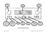
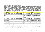
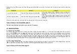
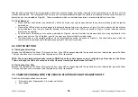
Figure 2 LED Sequence When Tachograph Carrying Out Automatic Functions (page 19)
If the tachograph has identified that an action is required, pushing the drawer in to unlock it for example, the three Driver LEDs and the
three Crew LEDs will flash alternately, changing from Driver LEDs illuminated/Crew LEDs extinguished to Crew LEDs illuminated/Driver
LEDs extinguished, as shown in Figure 3.
Figure 3 LED Sequence When Operator Action Required (page 19)
The LEDs are also used to indicate fault conditions, which are detailed in the
WARNING CODES
Section of this handbook (section 11.0).
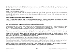
2.3 Mode Change Push-button
The Mode Change push-button, which is identified by a circular white dot (
O
), is used to select whether the display indicates the odometer
reading (total recorded distance since the tachograph was installed) or the trip reading (recorded distance since the trip reading was last
reset), and to adjust the time. Determining whether the odometer or trip reading is displayed is described in the
MODE SETTING
Section
while the clock adjustments are described in the
ADJUSTING THE TIME SETTING
Section.
2.4 Advance Push-button
The Advance push-button, which is identified by a white plus sign (
), is used to reset the trip value to zero and to alter individual field
settings of the digital clock. Setting the trip value to zero is detailed in the
MODE SETTING
Section while the clock adjustments are
described in the
ADJUSTING THE TIME SETTING
Section.
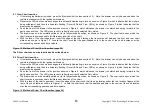
2.5 Eject Push-button
•
The Eject push-button, which is identified by the white legend
©
, is pressed prior to opening the drawer. When the Eject push-
button is pressed, a 3 mm radial line is drawn on the Driver chart between the Duty and Distance traces (to record that the drawer
is being opened), then the styli are withdrawn from the charts.
•
While the styli are retracting, the LED mode changes to the automatic sequence shown on Figure 2 (indicating that the
tachograph is carrying out internal functions – in this case stylus retraction). Once the styli are fully retracted, the LED mode
reverts back to the flashing sequence shown on Figure 3, indicating that the drawer can now be opened by the operator.
•
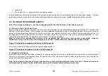
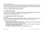
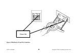
This is achieved by pushing the drawer at the oval emboss as shown on Figure 4 and then opening the drawer as shown on
Figure 5. After the drawer has been opened, the LEDs revert to their previously selected status indicating the current driver duty
(or duties if the tachograph is arranged for two driver operation).


