2400 User Manual
Copyright © 2004 Stoneridge Electronics Ltd
13
5.1 Crew Chart Insertion
•
If the tachograph drawer is closed, press the Eject push-button (see section 2.5). Note: the drawer can only be opened when the
vehicle is stationary with the ignition switched on.
•
Observe the LEDs as their mode changes to individually illuminating in turn, as shown on Figure 2 (which indicates that the styli are
being withdrawn), and then to alternately flashing (Driver LEDs and Crew LEDs), as shown on Figure 3 (which indicates that the
drawer can be opened).
•
Push the front of the drawer in the position shown on Figure 4, which will cause the drawer to unlatch and spring forward to the
partly open position. The LEDs then revert to reflect the currently selected Duty status
.
•
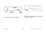
The drawer can now be carefully pulled out to its fully extended position, as shown on Figure 5. The chart table, upon which the
chart locates, is now exposed to facilitate easy insertion of the chart.
•
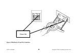
With the face of the chart uppermost, insert the edge of the chart through the transverse slot between the front and rear chart
platens, as shown in Figure 12. Locate the chart such that the pear-shaped hole in the centre of the chart locates over the
corresponding pear-shaped drive spindle.
Figure 12 Method of Crew Chart Insertion (page 23)
The Driver chart can now be inserted as described below.
5.2 Driver Chart Insertion
•
If the tachograph drawer is closed, press the Eject push-button (see section 2.5). Note: the drawer can only be opened when the
vehicle is stationary with the ignition switched on.
•
Observe the LEDs as their mode changes to individually illuminating in turn, as shown on Figure 2 (which indicates that the styli are
being withdrawn), and then to alternately flashing (Driver LEDs and Crew LEDs), as shown on Figure 3 (which indicates that the
drawer can be opened).
•
Push the front of the drawer in the position shown on Figure 4,
which will cause the drawer to unlatch and spring forward to the
partly open position. The LEDs then revert to reflect the currently selected Duty status
.
•
The drawer can now be carefully pulled out to its fully extended position, as shown on Figure 5. The chart table, upon which the
chart locates, is now exposed to facilitate easy insertion of the chart.
•
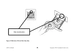
With the face of the chart uppermost, insert the edge of the chart such that its edge locates under the two location fingers at the
rear of the chart table, as shown in Figure 13. Locate the chart such that the pear-shaped hole in the centre of the chart locates
over the corresponding pear-shaped drive spindle.
Figure 13 Method of Driver Chart Insertion (page 24)


