2400 User Manual
Copyright © 2004 Stoneridge Electronics Ltd
12
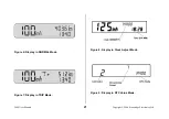
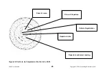
The DTC Value Display shows the DTC list position index, occurrence count and DTC number. Press the (
) repeatedly to browse through
the DTCs. If there are no errors stored, all values are replaced with ‘-‘ and the unit returns to normal mode after 5 seconds. Otherwise press
the
©
button to exit this mode.
4.3 DTC Time and Date Display Mode
The DTC display must be enabled in the 2400 tachograph for this mode to be possible. To enter the DTC Time and Date Display Mode,
press the (
O
) and (
) buttons simultaneously and release, then press the (
O
) button once. The screen of the tachograph would appear as
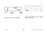
shown in Figure 10.
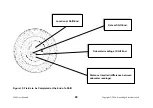
Figure 10 Display in DTC Time and Date Mode (page 22)
The DTC Time and Date Display shows the DTC list position index, date and time. If there are no errors stored all values are replaced with
‘-‘ and the unit returns to normal mode after 5 seconds. Otherwise press the
©
button to exit this mode.
5.0 INSERTION AND REMOVAL OF THE TACHOGRAPH CHART
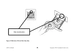
The Driver and Crew charts are both located within the tachograph drawer when in use. Each chart has a central location aperture, which
is ‘pear-shaped’. When the drawer is in the OPEN position, the drive mechanism can be rotated easily by hand. When the drawer is
closed, the drive mechanism is automatically driven to a position corresponding with the current time setting.
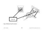
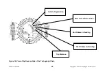
During normal operation, if the tachograph detects that the Driver chart is missing, the driver LEDs will alternately all light simultaneously
and all extinguish simultaneously a number of times (for 10-15 seconds), after which they will remain extinguished, as shown on Figure 11.
Similarly for the Crew, under normal operation, if the tachograph detects that the Crew chart is missing and the duty mode is NOT rest, the
Crew LEDs will alternately all light simultaneously and all extinguish simultaneously a number of times then remain extinguished (Note: if
the crew duty mode is rest the Crew LEDs will switch off without flashing).
Figure 11 Status of LEDs When Driver Chart Missing (Alternating On and Off) (page 22)
The chart insertion method for the Driver differs slightly from the insertion method for the Crew and thus the two procedures are individually
described below. It should also be noted that if Driver and Crew charts are both required, the Crew chart
must
be fitted first.
It is not necessary to fit the Crew chart when the tachograph is being used for single Driver operation. However, after the Driver chart is
installed and the drawer is closed, the Crew LEDs may indicate that a chart is missing (as described above).


