28
ATTACH THE
FOOT SWITCH
TO THE
BREAKOUT
BOARD
13
13
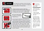
Exactly like we did is step 11,
we’re going to use our
housing to help with attaching
the footswitch.
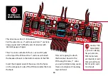
Insert the threaded shaft of the
footswitch into the OUTSIDE of
the housing and reattach the nut
and washer in the INSIDE.
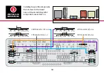
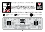
Align the holes in the breakout board with lugs on the
footswitch. Rotate the PCB/pots/breakout board and
footswitch until the pots rest somewhere comfortably
on the outside of the housing and solder.
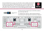
Making sure all the lugs are through the holes in the
breakout board and breakout board is flat against the
footswitch, solder the lugs to the breakout board.
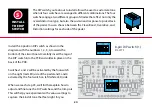
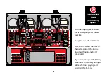
Once the solder has cooled on the lugs, remove the
washer and nut from the footswitch and remove
the PCB/breakout board/pots/footswitch group from
the housing. Reattach the washer and nut so they
don’t get lost.

