15
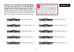
ON
ON
ON
ON
ON
ON
ON
ON
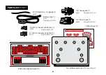
1N5817 rectifier diode (3)
#7522
1N914 rectifier diode (8)
#7521
ON
1N4001(1S1588) rectifier diode (4)
#101259
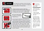
Free the printed circuit board (PCB) and breakout board from the frame by cutting the small
tabs with a string cutter or side cutter.
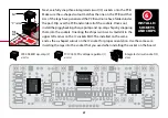
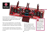
Insert the diode leads through the component side
(the side with the components’ values and outlines silkscreened in white). In many cases,
components must be inserted in a specific direction due to polarity, so follow the graphics
carefully. For example, diodes are polarized, so they must be installed in the correct orientation.
Solder the diodes on the opposite side of the board, known as the component side.
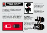
INSTALL 15
DIODES
2
2
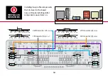
Note the stripe around
one end of the diode. This
marks the negative (minus) lead.
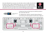
On the PCB, the printed outline of
the diodes also shows this stripe.
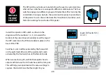
Install each diode to match the
direction shown. Place all diodes
with the wires pointing down,
through the component side.

