29
WD 14
With the PCB/breakout board,
pots and footswitch assembled
and free from the temporary
workspace on the outside of
the pedal housing, it’s time prep
the battery clip connection.
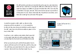
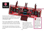
With the component side of
the PCB board group facing up
(breakout board should be in the lower left position),
thread the
two ends of
the wire leads
coming from
the battery clip
through the
tiny hole to the
left of the battery compartment opening in the PCB.
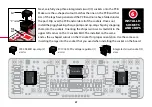
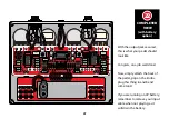
Guide the two leads under the PCB and tack the ends
to the back of the middle volume pot with a small
piece of tape.
Once you’ve threaded the
battery wires through the hole,
make a small knot with the wires to
prevent tension on the solder joints
when replacing the battery in the future.


